SediGraph III 5120 Service Interlock Circuitry
Mar 2010 2-21
The cell tip mechanism has a radius cut into the cell yoke holder that engages a stationary stud
on the X-ray tube side of the Analysis module wall. This in turn tilts the cell out (around 45°)
to facilitate filling and eliminating air bubbles in the cell assembly.
The calibrated PM tube’s (PN 511/25894/01) high voltage must be set to match the calibrated
voltage which is written on the tube.
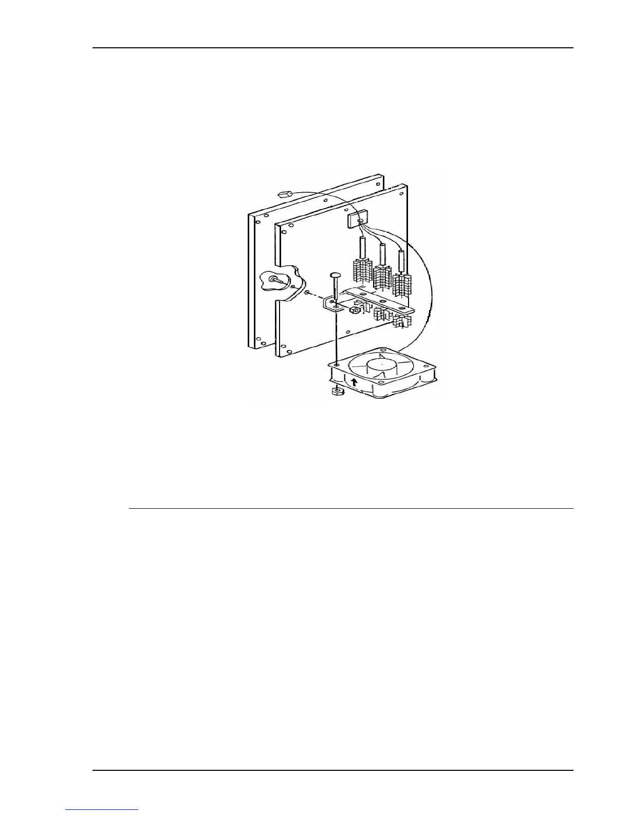
The Analysis module rear panel heater and fan assembly (PN 510/34002/04 whole picture) is
located at the rear of the Analysis module and contains three heaters and a fan assembly
(PN 510/60830/00).
Analysis Module Serviceable items:
004/25702/00 Spring Compression
510/57603/00 X-ray tube
510/60829/00 Cable, Cell Stepper Motor
510/60830/00 Cable, Cell Compartment Heater, Fan
510/25836/00 Pin, Shutter Interlock
510/33615/00 Service Kit, Anode Cable assy.
511/25600/00 Anti-Backlash nut
511/25894/01 Assy. PMT, Calibrated

 Loading...


