SmartFusion2 SoC FPGA - Cache Controller Configuration - Libero SoC v11.7
12 Revision 10
Board Settings
Connect the following jumpers on the SmartFusion2 Security Evaluation Kit, as described in Ta ble 5 .
Switch OFF the power supply switch SW7 on the board, while making the jumper connections.
Steps to Run the Design
The following steps describe how to run the design:
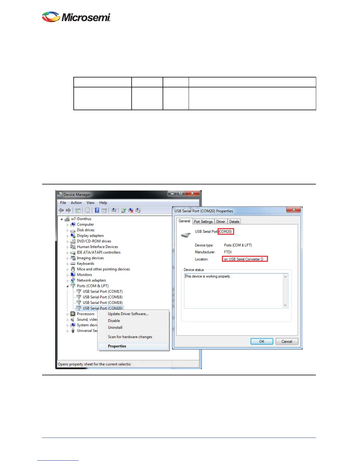
1. Connect the FlashPro4 programmer to the J5 connector of the SmartFusion2 Security Evaluation
Kit. Connect the J18 connector provided on the SmartFusion2 Security Evaluation Kit to the host
PC using the USB mini-B cable. Ensure that the USB to UART bridge drivers are automatically
detected by verifying the Device Manager, as shown in Figure 8.
Note: Copy the COM port number for serial port configuration. Ensure that the COM port location is
specified as on USB Serial Converter D, as shown in Figure 8.
2. If USB to UART bridge drivers are not installed, download and install the drivers from
www.microsemi.com/soc/documents/CDM_2.08.24_WHQL_Certified.zip.
Table 5 • SmartFusion2 Security Evaluation Kit Jumper Settings
Jumper Pin (From) Pin (To) Comments
J22, J23, J24, J8, J3 1 2 These are the default jumper settings of the
SmartFusion2 Security Evaluation Kit board. Make
sure these jumpers are set accordingly.
Figure 8 • USB to UART Bridge Drivers