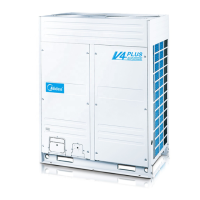
Do you have a question about the Midea V4+R Series and is the answer not in the manual?
| Brand | Midea |
|---|---|
| Model | V4+R Series |
| Category | Air Conditioner |
| Language | English |
Details the capacities and ranges for various indoor and heat recovery ventilator units.
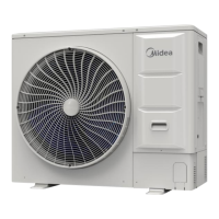
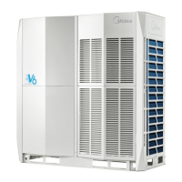
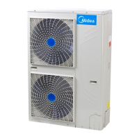
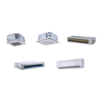
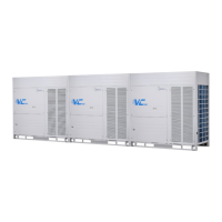
Illustrates the physical appearance of different indoor and outdoor unit types, including MS boxes.
Provides information on recommended combinations of outdoor units for system capacity, including branch joints.
Explains the limitations and calculation of indoor to outdoor unit capacity ratios for system design.
Identifies and locates key functional components within the outdoor units, with diagrams.
Presents schematic diagrams illustrating the refrigerant piping for different outdoor unit models.
Illustrates refrigerant flow during various operating modes like cooling, heating, and defrosting.
Provides a flowchart detailing the overall control logic and activation conditions for system operations.
Explains the reasons and conditions under which the system stops operation, including abnormal shutdowns.
Details control mechanisms for standby mode, focusing on crankcase heater operation based on temperature.
Describes procedures and component states during system startup for both cooling and heating modes.
Outlines component control during normal cooling and heating operations, including compressor output and fan control.
Details protection mechanisms for high pressure, low pressure, discharge temperature, compressor current, and inverter modules.
Covers specific control functions like outdoor unit duty cycling and oil return operation for system optimization.
Explains how to set PCB switches for operational parameters like start-up time, night silent time, and static pressure.
Shows the layout of components within the outdoor unit's electric control box for servicing.
Details ports, buttons, and components on the outdoor unit's main printed circuit board.
Lists error codes, their content, and remarks for diagnosing system faults and failures.
Provides step-by-step procedures for diagnosing and resolving specific error codes and system issues.
Provides tables correlating temperature sensor resistance with actual temperatures for diagnostic use.
Lists normal operating parameters for cooling and heating modes for system performance verification.



 Loading...