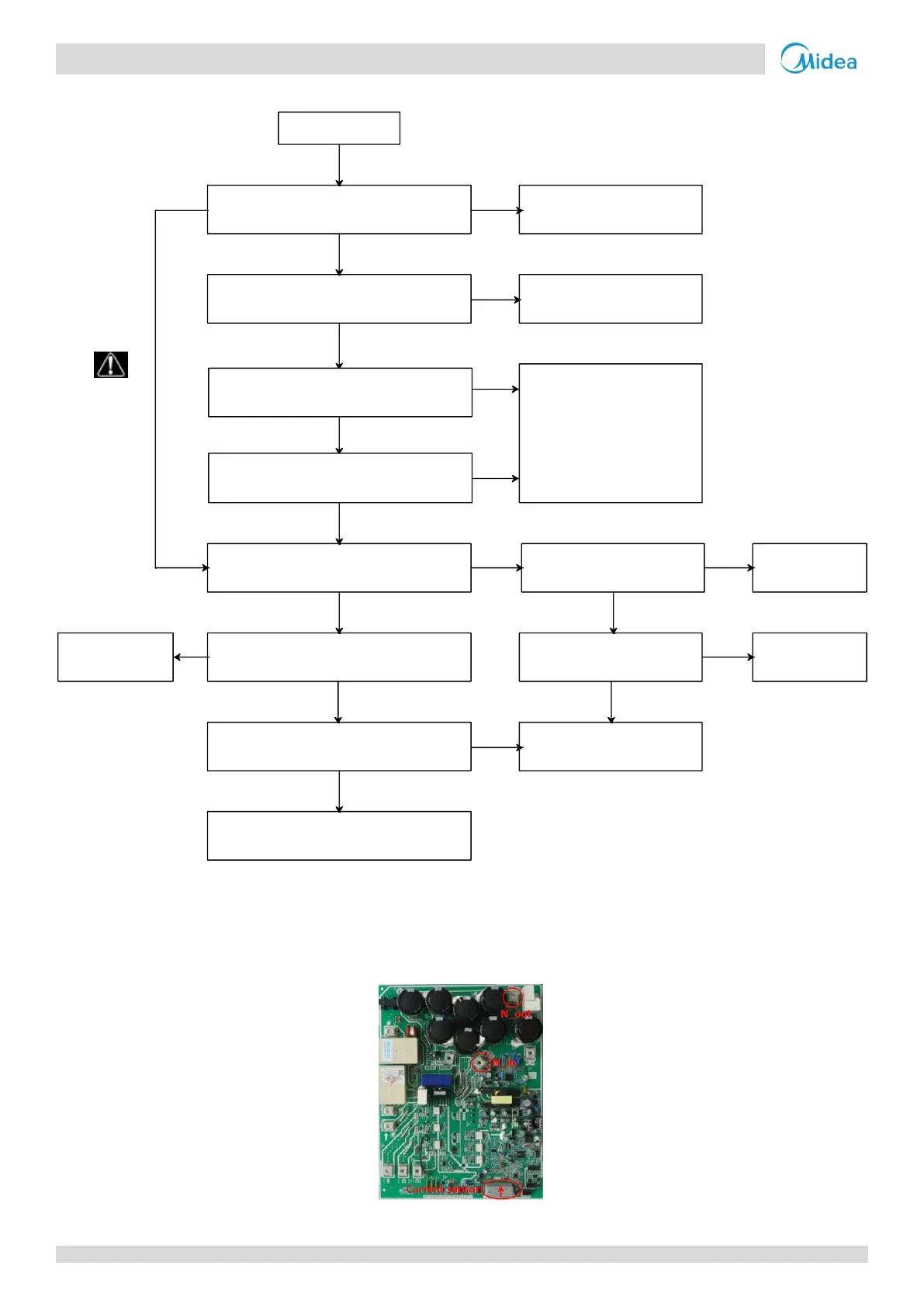
2. The DC bus wire should run from the N_in terminal on the inverter module, through the current sensor (in the direction indicated by the
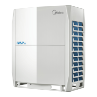
L0 protection
The DC bus wire connected incorrectly
1
Ensure the wire is
connected properly
The compressor wiring is connected
incorrectly
Reconnect the cables
based on wiring diagram
Replace the compressor
The inverter module is not well heat
dissipation
The IPM screws is loosen
Fasten IPM
screws again
The silica gel is coated not
well for heat radiation
Coat with silica
gel
The compressor has less than 12 hours
preheating before initial operating
Switch on power again to detect
whether the compressor can start
Refer to “P3 over current protection”
Replace the inverter
module
Ensure enough
preheating time
No
No
No
No
No
No
Yes
Yes
Yes
Yes
Yes
Yes
Yes
No
Yes
Yes
No
No
Disconnect
the power
supply
The resistance between 3 phases of
compressor is over 5Ω
The insulation resistance of
compressor is less than 100kΩ