V6 VRF 50Hz
63
Part 5 - Electrical Components and Wiring Diagrams
How to exit specified menu mode:
Table 5-2.4: Exit specified menu mode method:
Long press SW6 “OK” button when the digital
display is not in menu selection state
After running 120 minutes
After running 4 days or both
two compressors are failed
Long press SW6 “OK” button when the digital
display is not in menu selection state
Select power limitation mode 1 “n41”
Auto snow-blowing mode 1 (2)
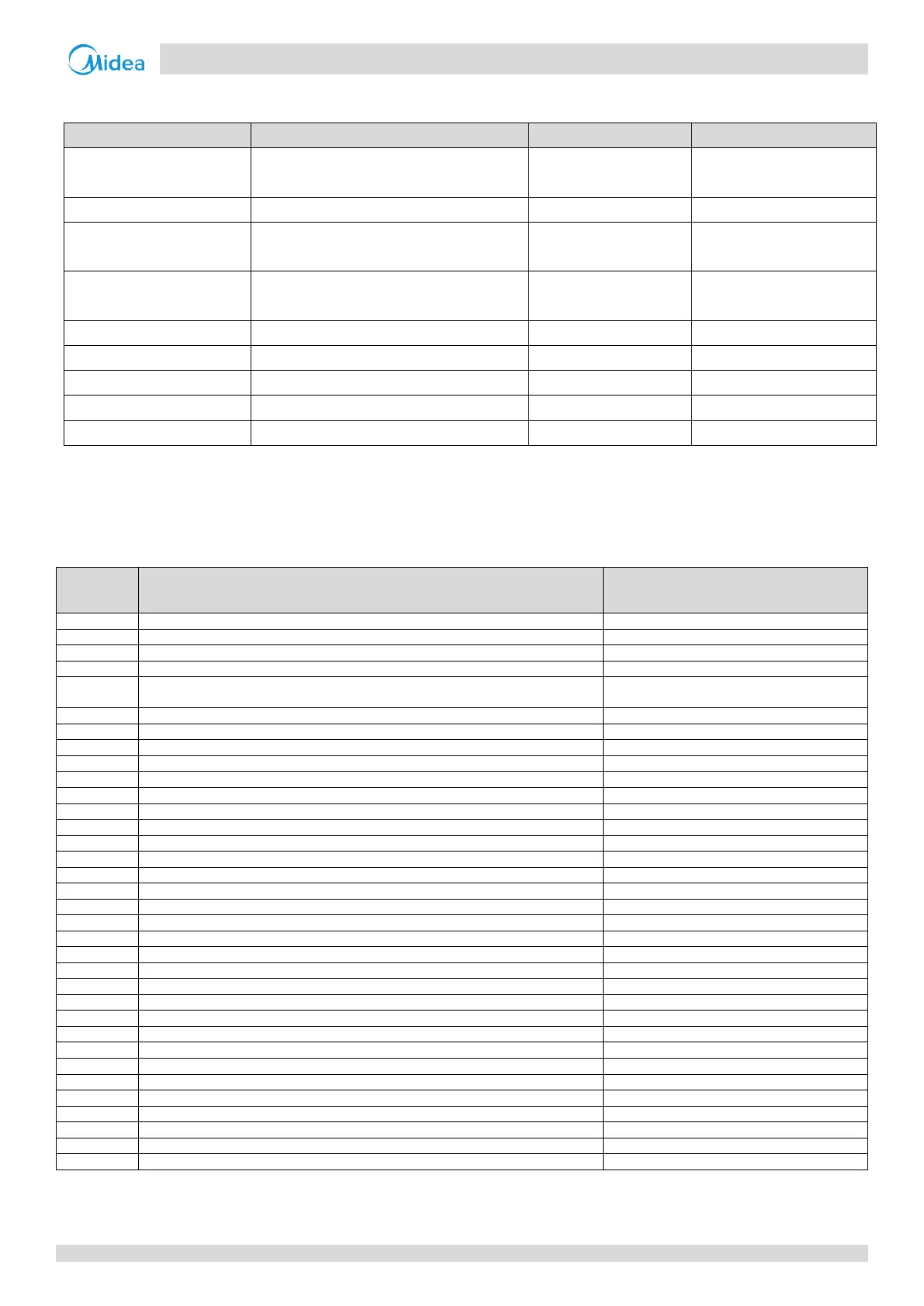
UP / DOWN system check button 2.2.4
Before pressing UP or DOWN button, allow the system to operate steadily for more than an hour. On pressing UP or DOWN
button, the parameters listed in Table 5-2.5 will be displayed in sequence.
Table 5-2.5: System check
Parameters displayed on DSP2
Master unit: 0; slave units: 1, 2, 3
Displayed on master unit PCB only
Number of indoor units as set on PCB
Displayed on master unit PCB only
Total capacity of outdoor unit
Only available for master unit, displayed on slave
units has no sense
Total capacity requirement of indoor units
Displayed on master unit PCB only
Total corrected capacity requirement of indoor units
Displayed on master unit PCB only
Outdoor unit actual operating capacity
Indoor heat exchanger pipe (T2/T2B) temperature (°C)
Actual value = value displayed
Main heat exchanger pipe (T3) temperature (°C)
Actual value = value displayed
Outdoor ambient (T4) temperature (°C)
Actual value = value displayed
Plate heat exchanger cooling refrigerant inlet (T6A) temperature (°C)
Actual value = value displayed
Plate heat exchanger cooling refrigerant outlet (T6B) temperature (°C)
Actual value = value displayed
Inverter compressor A discharge temperature (°C)
Actual value = value displayed
Inverter compressor B discharge temperature (°C)
Actual value = value displayed
Inverter module A heatsink temperature (°C)
Actual value = value displayed
Inverter module B heatsink temperature (°C)
Actual value = value displayed
Plate heat exchanger cooling refrigerant outlet temperature minus inlet temperature (°C)
Actual value = value displayed
Discharge superheat degree (°C)
Actual value = value displayed
Inverter compressor A current (A)
Actual value = value displayed
Inverter compressor B current (A)
Actual value = value displayed
Compressor discharge pressure (MPa)
Actual value = value displayed × 0.1
Number of indoor units currently in communication with master unit
Actual value = value displayed
Number of indoor units currently operating
Displayed on master unit PCB only
Table continued on next page …