V6
66
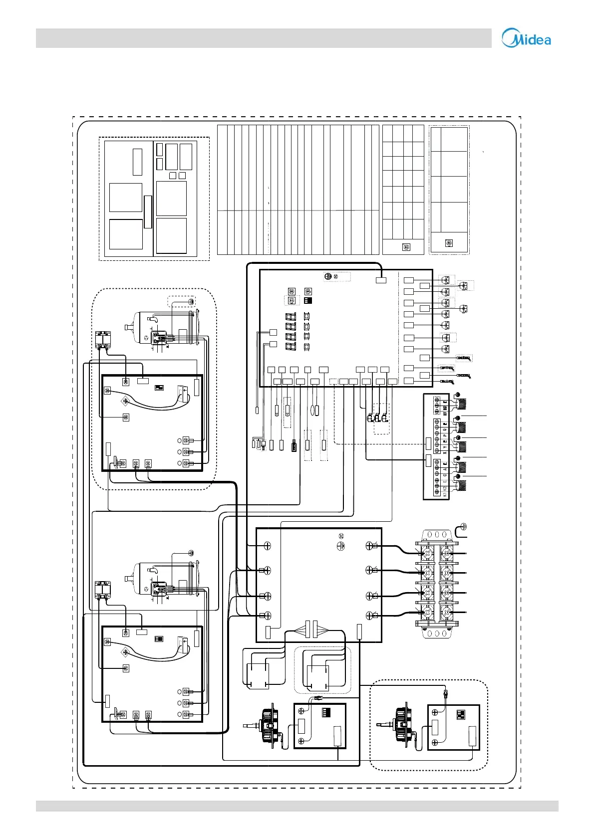
Midea V6 Series Service Manual
4
8-2
Figu
VRF 50
iring Dia
HP
e5‐4.1:8‐28H
RA
RB
Red(Black)
B
l
u
e
White
Red(Black)
z
grams
wiringdiagra
CN5
P_out
CN3
N
_
i
n
CN1
P_in
_
U
V
w
CN4
S7
CN6
CN7
CN11
L1
L2
L3
CN5
P_out
CN3
N
_
i
n
CN1
P_in
_
U
V
w
CN4
S7
CN6
CN7
CN11
L1
L2
L3
ON
ON
k
L8
L8
Red
Black
C
o
m
p
r
e
s
s
o
r
Red(Black)
Red
White
B
l
u
e
C
o
m
p
r
e
s
s
o
r
Red
White
B
l
u
e
Red(Black)
Red
Black
XT1
Main
board
AC filter
board
Up layer
Comm. board
CN2
CN2
Black Blue
m
U
V W
CN8(CN9)
IC17
COMP A
U
V W
IC17
COMP B
CN12 CN13 CN14
CN12 CN13 CN14
1
2
1
2
Black
Blac
Bla
d
r
i
v
e
b
o
a
r
d
A
Red
Black
B
l
u
e
d
r
i
v
e
b
o
a
r
d
B
Red
Black
B
l
u
e
BR1
BR2
C
o
m
p
r
e
s
s
o
r
d
r
i
v
e
b
o
a
r
d
B
C
o
m
p
r
e
s
s
o
r
d
r
i
v
e
b
o
a
r
d
A
DC fan drive
board A
DC fan drive
board B
Down layer
PCBA Layout
Brown
CN8(CN9)
+
-~
~
BR1
TP1-PRO
TP2-PRO
L-PRO
’
’
’
’
’
FAN A
Red White Blue
Red White Blue
Black
Red
B
l
u
e
FAN A/B
-
-
EEVA/EEVB/EEVC
HEATA/HEATB
BR1/BR2
COMP A/COMP B
DC Fan
Hi
h/Low
ressure ON/OFF switch
Electronic expansion valve
Crankcase heater
Inverter compressor A/B
CODE NAME
Single-phase Bridge Rectifier
H-PRO
L-PRO
CN19
H-PRO
CN18
DSP1 DSP2
CN17
H-YL1T7C1
OKUPMENU DOW N
ENC3
S12
IN_NUM
TF1
T7C1
CN4
T7C2
CN5 CN8
T6A
C
T7C2
CN1
T4 T3
CN3
TF2
CN3_1
TF2
CN15
T6A
T4
T3
ENC2
POWER
CN12
CN9
CN10
CN11
CN3
N
P
H-YL1
CN31(CN32)
1
ON
2 3
+~
BR2
CN32(CN31)
ENC1
NUM_ S
(Left)
AC filter board
Red
B
l
u
e
B
l
u
e
Black
DC fan drive
ST1
T3
H-YL1
RA/RB
IC17
SV2/SV4-SV9
Main exchanger pipe temperature
n
r
4-way valve
Reactance
Current sensor
High pressure sensor
Solenoid valve
L8
Current sensor
CN100
8_1
6B
CN7
EEV
CN27
O-FAN
CN26
O-C
CN20
O-O
EEVA
T6B
CN25
N
CN5
CN51
L1
L2 L3
CN6 CN7 CN8
1
ON
2 34
C
N
1
(
C
N
4
)
-~
SW1
B
l
u
e
Black
Main board
TP1/TP2-PRO
T4
T7C1/T7C2
TF1/TF2
Plate heat exchanger cooling refrigerant
inlet/outlet temperature sensor
T6A/T6B
Outdoor ambient temperature sensor
Discharge temperature ON/OFF switch
Discharge temperature sensor
Inverter-module heatsink temperature
sensor
CN21(CN22)
CN28
O-D
FAN B
CN84
CN45
CN67_1
CN66_1
CN85
CN83
CN46
CN44
CN43
CN47
CN67
CN66
CN72
EEVC
EEVC
CN71
EEVB
EEVB
ST1 SV4 SV5 SV7 SV8A SV9
SV6 SV8BHEATB
HEATBHEATA
HEATA
CN30
CN82
N-ON
CN41
SV2
(Right)
Red
Black
White
B
l
u
e
Red
Black
White
B
l
u
e
Black
Black Black Black
Comm. board
capacity
setting
ENC2
1
8HP
2
10HP
3
12HP
4
14HP
5
16HP
6
18HP
capacity
setting
ENC2
7
22HP
8
24HP
9
26HP
A
28HP
0
20HP
ENC2
POWER
CN3
N
P
ST1 SV4 SV5 SV7 SV8A SV9
SV6
SV8B
HEATA
HEATA
H EAT B
H EAT B
ABC
XT1
N
SV2
1
ON
2 34
C
N
1
(
C
N
4
)
SW1
DC fan drive
board B
Power in
Attention
:
ENC2 is factory setting
,
do not change at will
;
ENC1 is available in multi outdoor unit s
stem.
To
kilowatt-
hour
To
centrali-
zed
controller
To
indoor units
communi-
cation
To
outdoor
units comm-
unication bus
Reserved
Outdoor unit
address
setting
ENC1 0
Master
unit
(Factory
setting)
12
ENC1
NUM_S
Slave
unit 1
Slave
unit 2
The dotted frame section is use by some models.
This connection diagram is for reference only.
Please refer to the actual product.
bus