V6 VRF 50Hz
93
Part 6 - Diagnosis and Troubleshooting
Procedure 2.12.5
Electronic expansion valve coil
connection on main PCB is loose
1
Ensure the sensor is connected properly
Electronic expansion valve coil has
malfunctioned
2
Notes:
1. Electronic expansion valve coil connections are port CN70, CN71 and CN72 on the main PCB (labeled 18, 19 and 20, respectively, in Figure 5-2.1 in Part 5,
2.1 “Ports”).
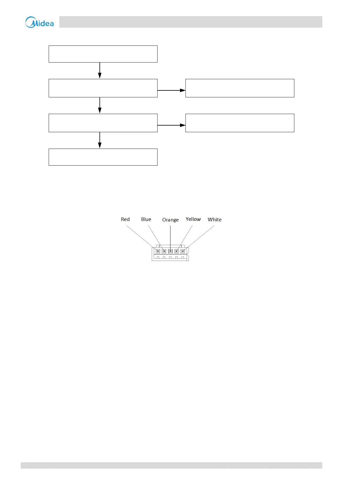
2. The normal resistances between EXV coil wiring terminals RED and white / yellow / orange / blue are 40-50Ω. If any of the resistances differ from the value,
the EXV coil has malfunctioned.
Figure 6-2.3: EXV coil wiring terminals