EasyManuals Logo

Midea V6 Series User Manual

Midea V6 Series
136 pages
To Next Page IconTo Next Page
To Previous Page IconTo Previous Page
Page #17 background imageLoading...
Page #17 background image
V6 VRF 50Hz
16
Midea V6 Series Service Manual
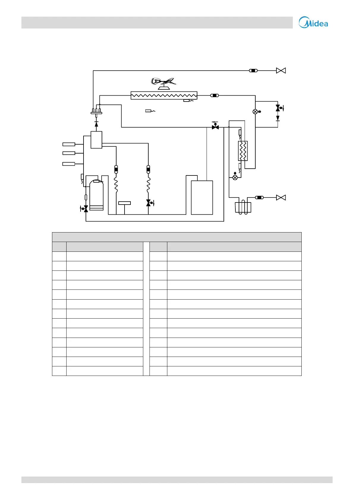
2 Piping Diagrams
8/10/12HP
Figure 2-2.1: 8/10/12HP piping diagram
Legend
No.
Parts name
No.
Parts name
1
Compressor
14
Plate heat exchanger
2
Discharge temperature switch
15
Accumulator
3
High pressure switch
16
Heat exchanger cooling electric control box
4
High pressure sensor
T3
Heat exchanger temperature sensor
5
Oil separator
T4
Outdoor ambient temperature sensor
6
Four-way valve
T6A
Plate heat exchanger inlet temperature sensor
7
Heat exchanger
T6B
Plate heat exchanger outlet temperature sensor
8
Electronic expansion valve (EXV)
T7C1
Compressor A discharge temperature sensor
9
Low pressure switch
T7C2
Compressor B discharge temperature sensor
10
Fan motor
SV4
Oil return valve
11
Fan
SV5
Fast defrosting (in heating) and unloading (in cooling) valve
12
Stop valve (liquid side)
SV6
Refrigerant bypass EXV valve
13
Stop valve (gas side)
SV8A
Compressor A vapor injection valve
7
1
15 12
9
3
2
4
5
6
11
10
9
14
8
8
13
EXVA
EXVC
E
S
C
T3
T4
T6B
T7C1
T7C2
T6A
SV8A
SV4
SV5
SV6
16

Table of Contents

Questions and Answers:

Question and Answer IconNeed help?

Do you have a question about the Midea V6 Series and is the answer not in the manual?

Midea V6 Series Specifications

General IconGeneral
BrandMidea
ModelV6 Series
CategoryAir Conditioner
LanguageEnglish

Related product manuals