V6 VRF 50Hz
27
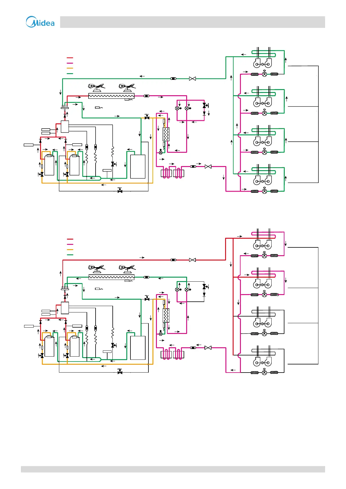
Part 2 - Component Layout and Refrigerant Circuits
Oil return operation in heating mode and defrosting operation
Figure 2-3.11: 18/20/22HP refrigerant flow during oil return operation in heating mode and during defrosting operation
Heating operation
Figure 2-3.12: 18/20/22HP refrigerant flow during heating operation
16
480 steps
Filter
Filter
480 steps
Unit on
Thermostat off
Unit on
Thermostat on
Unit on
Thermostat on
Unit off
Filter
Indoor unit operation
Filter
480 steps
Filter
Filter
480 steps
Filter
Filter
Fan
off
Fan
off
Fan
off
Fan
off
7
1
1
15
12
9
3
4
5
6
11
11
10 10
14
8
8
8
13
EXVBEXVA
EXVC
E
S
C
T3
T4
2
T7C1
T7C2
T6B
T6A
SV8A
SV8B
SV9
SV4
SV5
SV6
2
High temperature, high pressure gas
High temperature, high pressure liquid
Medium temperature, medium pressure gas
Low temperature, low pressure
Closed
Closed
Filter
Filter
Unit on
Thermostat off
Unit on
Thermostat on
Unit on
Thermostat on
Unit off
Filter
Indoor unit operation
Filter
Normal control
Normal control
Filter
Filter
Filter
Filter
Fan
on
Fan
off
Fan
on
Fan
on
7
1
1
15
12
9
3
4
5
6
11
11
10 10
14
8
8
8
13
EXVBEXVA
EXVC
E
S
C
T3
T4
2
T7C1
T7C2
T6B
T6A
SV8A
SV8B
SV9
SV4
SV5
SV6
2
High temperature, high pressure gas
High temperature, high pressure liquid
Medium temperature, medium pressure gas
Low temperature, low pressure