EasyManuals Logo
Home>Midea>Air Conditioner>V6 Series

Midea V6 Series User Manual

Midea V6 Series
136 pages
To Next Page IconTo Next Page
To Previous Page IconTo Previous Page
Page #48 background imageLoading...
Page #48 background image
V6 VRF 50Hz
47
Part 3 - Control
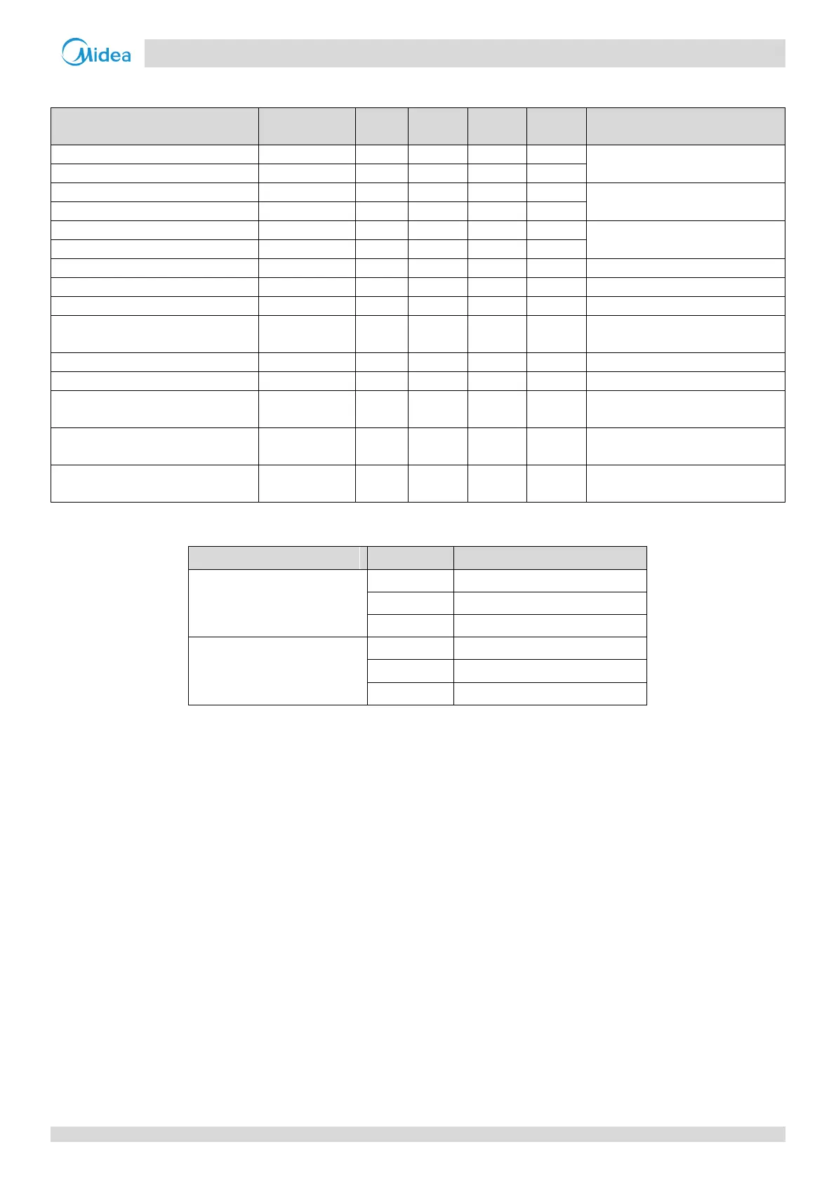
Tables 3-7.3 and 3-7.4 show component control during oil return operation in heating mode.
Table 3-7.3: Outdoor unit component control during oil return operation in heating mode
Component
Wiring diagram
label
8-12HP
14-16HP
18-28HP
30-32HP
Control functions and states
Inverter compressor A
COMP(A)
Fixed frequency
Inverter compressor B
COMP(B)
DC fan motor A
FANA
Fan speed controlled according to
discharge pressure
DC fan motor B
FANB
Electronic expansion valve A
EXVA
Position 480 (steps)
Electronic expansion valve B
EXVB
Electronic expansion valve C
EXVC
Position 96 (steps)
Four-way valve
ST1
Off
Solenoid valve (oil balance)
SV4
Normal control
Solenoid valve (fast defrosting (in
heating) and unloading (in cooling))
SV5
On
Solenoid valve (EXV bypass)
SV6
On
Solenoid valve (indoor units bypass)
SV7
Normal control
Solenoid valve (inverter compressor
A vapor injection)
SV8A
Off
Solenoid valve (inverter compressor
B vapor injection)
SV8B
Off
Solenoid valve (inverter compressor
B pressure balance)
SV9
Open before compressor B startup
Table 3-7.4: Indoor unit component control during oil return operation in heating mode
Component
Unit state
Control functions and states
Fan
Thermo on
Off
Standby
Off
Thermo off
Off
Electronic expansion valve
Thermo on
480 (steps)
Standby
480 (steps)
Thermo off
480 (steps)

Table of Contents

Questions and Answers:

Question and Answer IconNeed help?

Do you have a question about the Midea V6 Series and is the answer not in the manual?

Midea V6 Series Specifications

General IconGeneral
BrandMidea
ModelV6 Series
CategoryAir Conditioner
LanguageEnglish

Related product manuals