V6 VRF 50Hz
59
Part 5 - Electrical Components and Wiring Diagrams
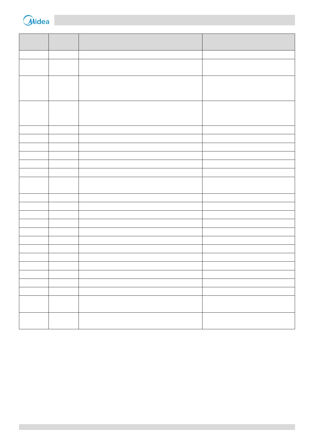
Table 5-2.1: Main PCB ports
Low pressure switch connection
High pressure switch and discharge temperature switch(es)
connections
Compressor top temperature sensor (single compressor
units) or compressor A compressor top temperature sensor
(dual compressor units) connection
Discharge pipe temperature sensor (single compressor units)
or compressor B compressor top temperature sensor (dual
compressor units) connection
Inverter module temperature sensor A connection
Inverter module temperature sensor B connection
High pressure sensor connection
Inverter compressor A and B current sensor connections
Plate heat exchanger inlet temperature sensor connection
Outdoor ambient temperature sensor and outdoor heat
exchanger temperature sensor connections
Plate heat exchanger outlet temperature sensor connection
Communication port to outdoor units
Communication port to compressor drive board
Communication port to fan drive board
Control port of relay for AC filter board
Power supply to compressor crankcase heater
Four-way valve drive ports
Solenoid valve drive ports
Power input of main board
220V AC between A/B/C and N;
380V AC between A,B and C
 Loading...