English-54
004-1055-00
TP210 Rev. A
© 2013 Midmark Corp. | 60 Vista Drive Versailles, OH 45380 USA | 1-800-643-6275 | 1-937-526-3662 |
[Revised: mo/dd/yr]
J14
J13
J12
J11
J10
J8
F3
F2
J9
C2
TPC3
TPB1
TPB2
TPB3
J15
TPA
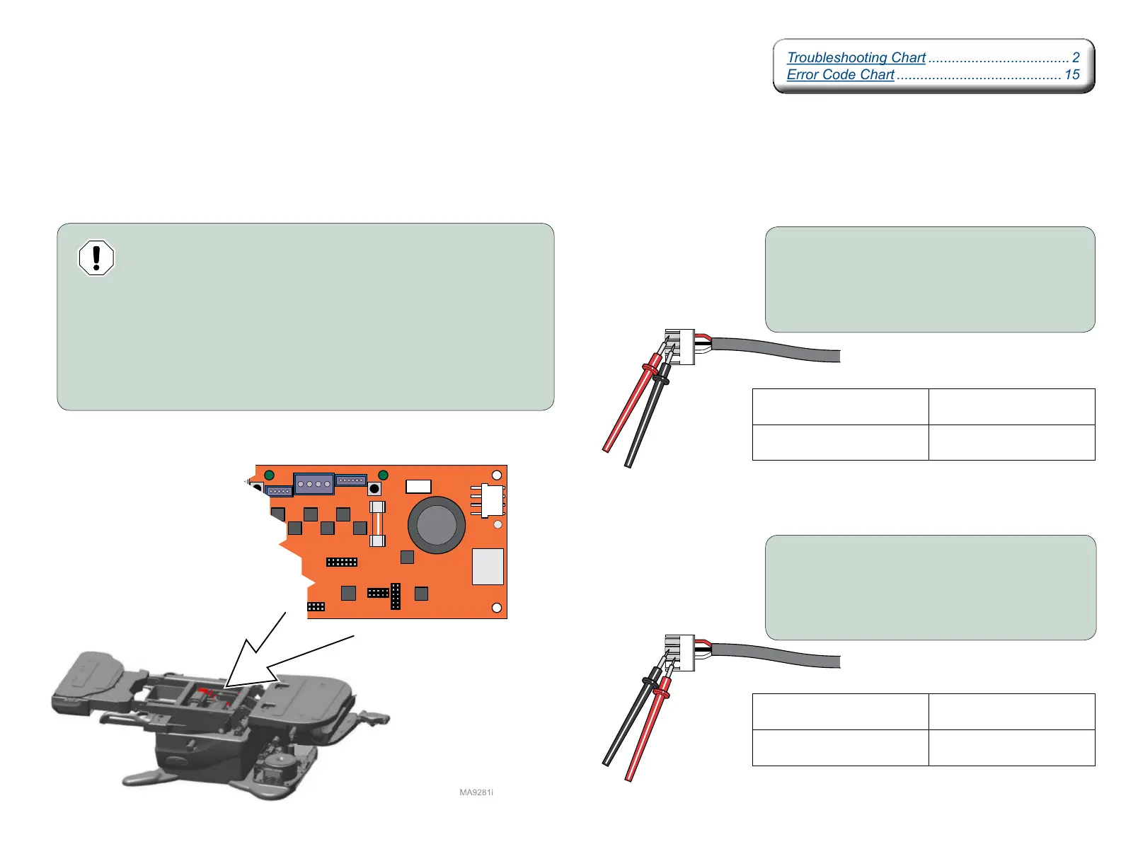
Motor Control Hub PC Board Supply Power
Isolating a Malfunction
The Power Supply PC Board supplies approximately + 36 VDC thru the Red wire, and - 36 VDC
thru the White wire to the Motor Control Hub PC Board using the Black wire as the common.
Equipment Alert
Always remove power from table before disconnecting or connecting
J13 on Motor Control Hub PC Board or damage to PC Board may occur.
Step 1:
A) Disconnect power to the table.
B) Disconnect J-13 harness from Motor Contol PC Board.
C) Connect power to table.
D) Set meter to VDC.
Meter Reading Required Action
+ 36 VDC
Replace Motor Control Hub
PC Board.
0 VDC
Replace Power Supply
PC Board.
Step 2: Place the Black meter probe on the
Black wire (common) of J-13 harness.
Place the Red meter probe on the
Red wire of J-13 harness.
Step 3: Place Black meter probe on the
Black wire (common) of J-13 harness.
Place the Red meter probe on the
White wire of J-13 harness.
Meter Reading Required Action
- 36 VDC
Replace Motor Control Hub
PC Board.
0 VDC
Replace Power Supply
PC Board.
Troubleshooting Chart .................................... 2
Error Code Chart .......................................... 15
Troubleshooting Chart .................................... 2
Error Code Chart .......................................... 15