English-63
004-1055-00
TP210 Rev. A
© 2013 Midmark Corp. | 60 Vista Drive Versailles, OH 45380 USA | 1-800-643-6275 | 1-937-526-3662 |
[Revised: mo/dd/yr]
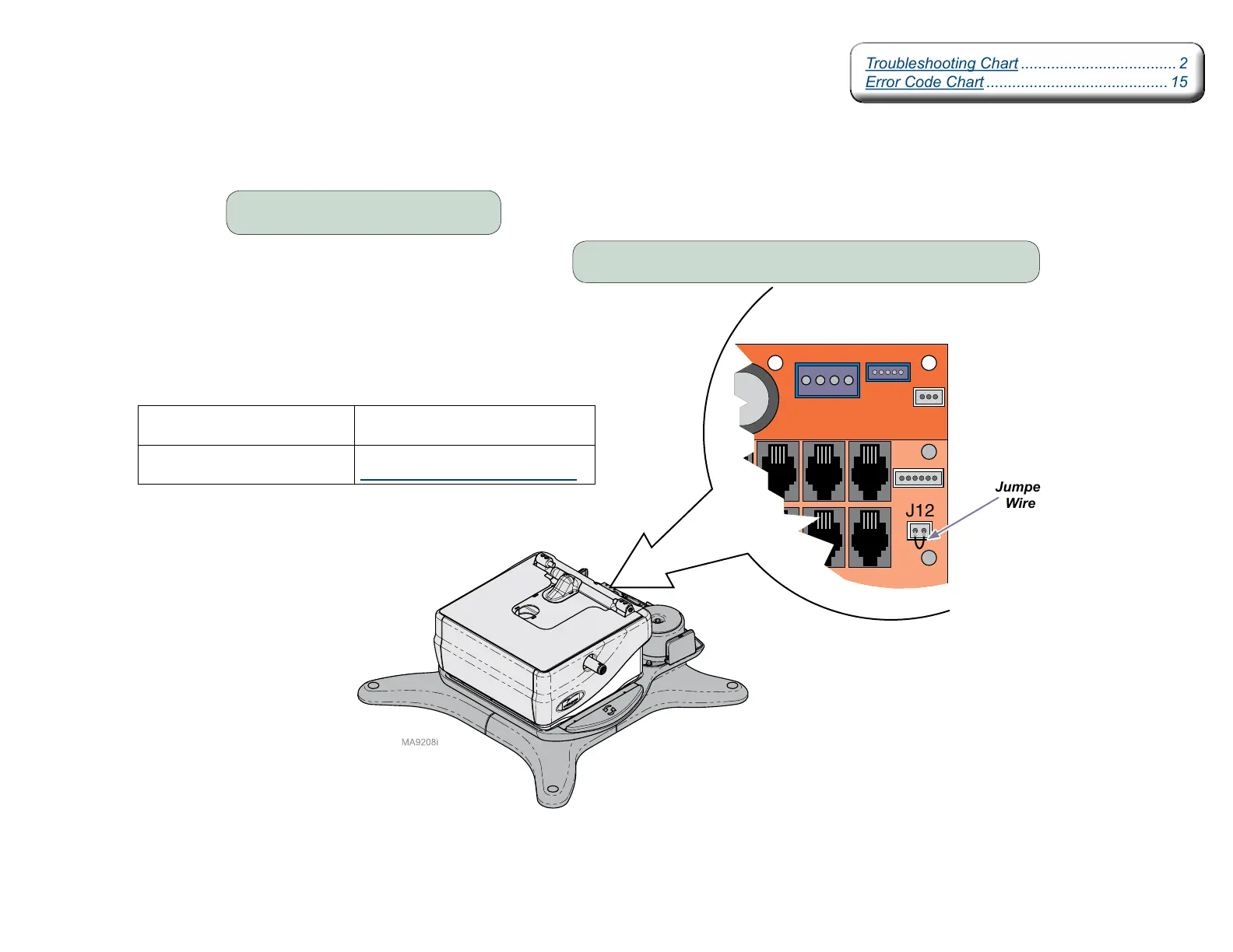
Rotational Base Brake System - continued
Rotational Brake PCB Input Test
Jumper
Wire
Result Required Action
Rotational Brake
Activates
PC board is OK.
Test brake pedal switch(s).
Rotational Brake
Does Not Activate
Refer to:
Rotational Brake PCB Output Test.
Step 1: Remove PC Board cover.
Step 2: Place jumper wire at J12 on Power Supply PC Board.
Troubleshooting Chart .................................... 2
Error Code Chart .......................................... 15
Troubleshooting Chart .................................... 2
Error Code Chart .......................................... 15