English-64
004-1055-00
TP210 Rev. A
© 2013 Midmark Corp. | 60 Vista Drive Versailles, OH 45380 USA | 1-800-643-6275 | 1-937-526-3662 |
[Revised: mo/dd/yr]
J4
J6
J12
J5
J7
J6
J1
J16
J4
F5
J6
J12
J5
J7
J6
J1
J16
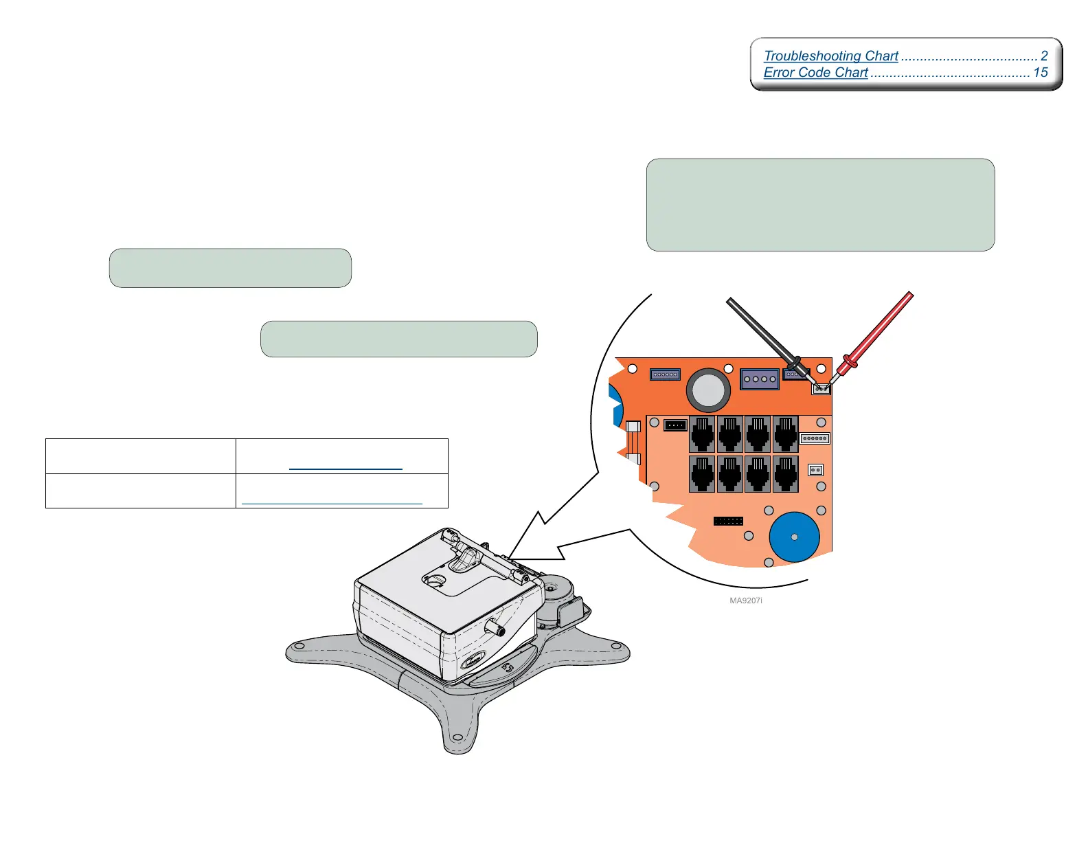
Rotational Base Brake System - continued
Rotational Brake PCB Output Test
Step 1: Remove PC Board cover.
Step 3: Place meter probes on middle and right
pins at J4 on Power Supply PC Board.
Note: If no voltage is detected, press & release the brake pedal,
then check again.
Meter Reading Required Action
12-24 VDC PC board is OK.
Perform Electro-magnet Test.
0 VDC Refer to:
Rotational Brake PCB Input Test.
Step 2: Press and release brake pedal.
Troubleshooting Chart .................................... 2
Error Code Chart .......................................... 15
Troubleshooting Chart .................................... 2
Error Code Chart .......................................... 15