Preva Installation/Service Manual, 00-02-1577, Revision E01
33
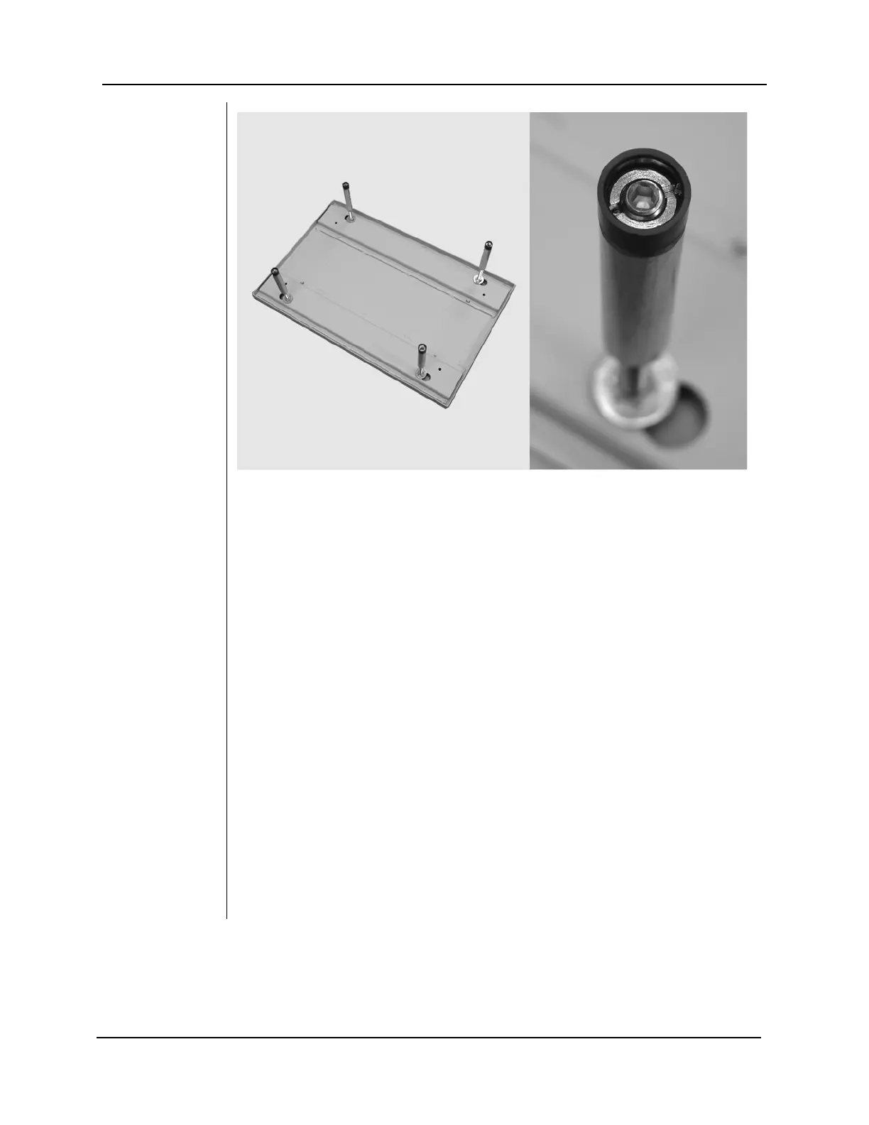
Figure 17
Support Plate for
Metal Stud Wall
Mount
Plate (30-
A2042)
1. Select the 5/16”-18 x 1” long hex bolts [H1-00-S23100-01].
2. Put the hex bolts through the mounting holes on the wall plate and loosely
tighten. Be sure that the power wire extends through the opening in the wall
plate.
3. Level the wall plate.
4. Tighten the hex bolts
Control Unit
Front Cover
1. Open the shipping carton and locate the Control Unit in the first level of the
carton.
2. Remove the socket flathead screw from the front cover of the Control Unit.
3. Carefully remove the front cover.
4. Place the front cover and the screw in a safe location for later reassembly.
Control Unit
1. Select the 5/16”-18 x 7/8” long socket cap screws [H1-15-S23088-01] and
washers [H1-NA-S12000-01].
2. Put the one screw and washer through the upper mounting hole of the Control
Unit.
3. Place the Control Unit on the wall and loosely tighten the upper screw.
4. Put the other screw and washer through the lower mounting hole of the
Control Unit and loosely tighten. Be sure that the power wire extends through
the opening at the bottom of the Control Unit.
5. Place a level on the Control Unit bearing parallel to the wall. Level the Control
Unit.
6. Tighten the upper and lower screws.
7. After the Preva is installed, slide covers on the wall plate and fasten with the
provided (8) screws [H1-64-S17050-01].