Preva Installation/Service Manual, 00-02-1577, Revision E01
65
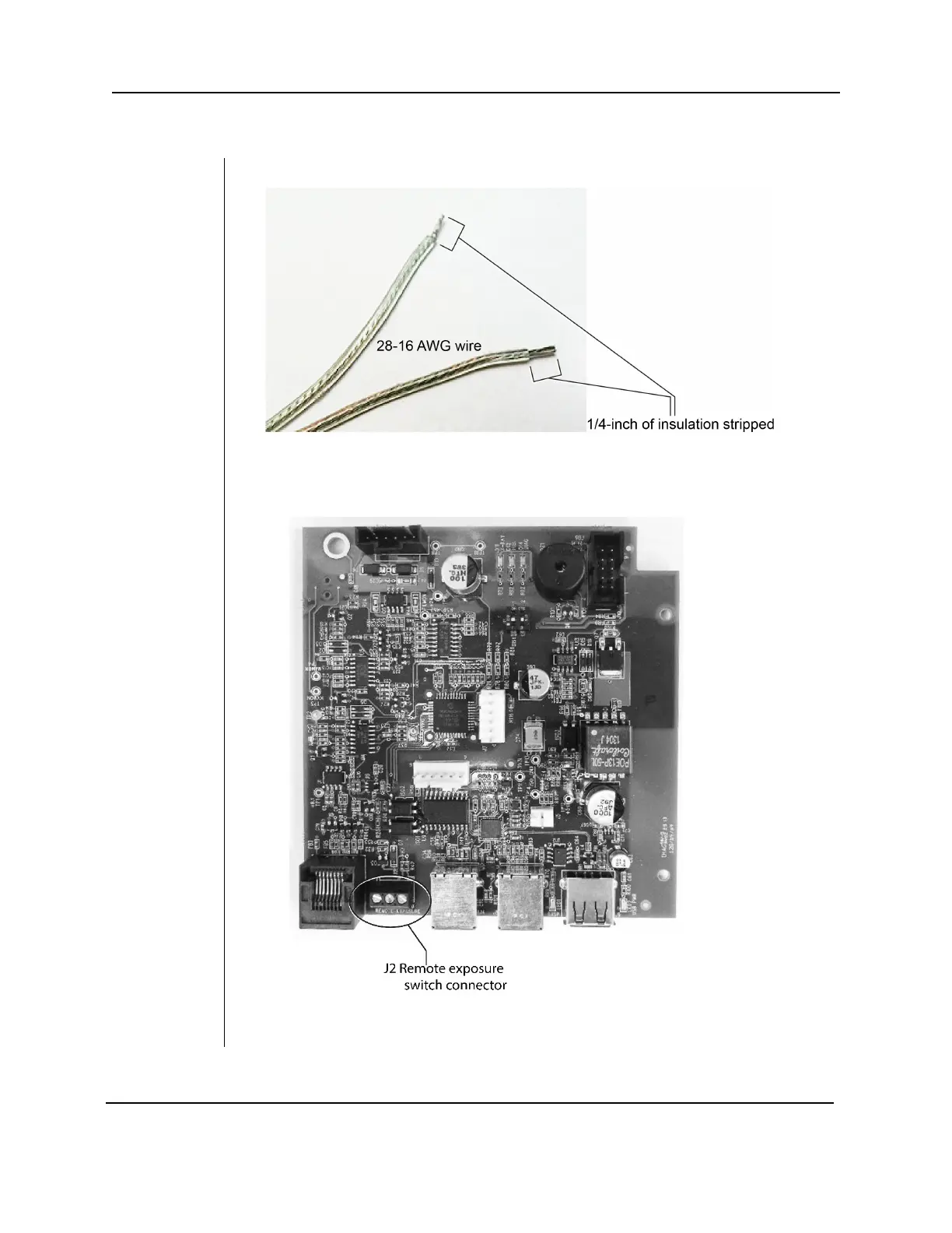
Connecting to a Generic 2 Wire Remote Exposure Switch
Figure 46
Stripping
insulation
from the
wires
1. Strip ¼-inch of insulation from two 28-16 AWG wires.
2. Remove the control unit cover and the logic board locking screw.
3. Swing open the logic board and locate terminal block J2 on the power supply
control board (30-08160), as shown in Figure 47.
Figure 47
Installing
the remote
exposure
switch