Preva Installation/Service Manual, 00-02-1577, Revision E01
64
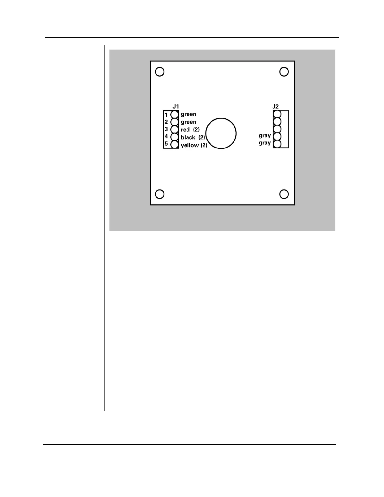
Figure 45
Series Switch
Configuration
5. Make sure the two gray wires from the pushbutton switch are connected to
terminals 1 and 2 of J2.
6. Screw the inner section of enclosure #1 to the junction box using the two
screws provided. If the cable is routed on the surface of the wall, make sure
it sits in the notch on the bottom of the enclosure. Confirm that no wires are
being pinched between the junction box and the enclosure.
7. Hook the outer section of the enclosure onto the inner section at the top.
Push the wires all the way into the enclosure and fasten the two pieces at
the bottom with the 6-32 x 5/16-inch screw.
8. Cut the handset connector from the end of the cable that will connect to
switch enclosure #2 and strip about 1 ½-inch of the white jacket.
9. Strip ¼-inch of insulation from each of the conductors.
10. Connect the cable conductors to terminal block J1 on the PCB of switch
enclosure #2 as shown in Figure 43 (the same as the single switch
configuration).
11. Make sure the two gray wires from the pushbutton switch are connected to
terminals 1 and 2 of J2.
12. Screw the inner section of enclosure #2 to the junction box using the two
screws provided. If the cable is routed on the surface of the wall, make sure
it sits in the notch on the bottom of the enclosure. Confirm that no wires are
being pinched between the junction box and the enclosure.
13. Hook the outer section of the enclosure onto the inner section at the top.
Push the wires all the way into the enclosure and fasten the two pieces at
the bottom with the 6-32 x 5/16-inch screw.