Preva Installation/Service Manual, 00-02-1577, Revision E01
62
Single Switch
1. Route the cable for the Remote Exposure Switch from the Preva mounting
location to the Remote Exposure Switch mounting location. This can be
done through conduit or on the wall surface. For either method, a 2” x 4”
junction box should exist where the Remote Exposure Switch is to be
mounted.
2. Thread the cable end with the handset connector through the opening in the
wall mount cover from the inside and connect it to the Operator Panel. If the
cable is routed on the surface of the wall, it should enter the wall mount
cover through the notch on the left of the power switch.
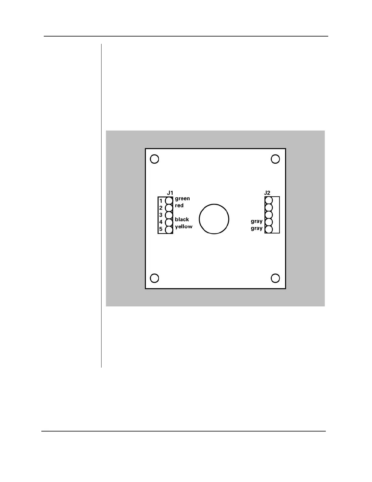
3. Connect the cable conductors on the opposite end of the cable to terminal
block J1 on the PCB in the switch enclosure as shown in Figure 43.
Figure 43
Single Switch
Configuration
4. Make sure the two gray wires from the pushbutton switch are connected to
terminals 1 and 2 of J2.
5. Screw the inner section of the enclosure to the junction box using the two
screws provided. If the cable is routed on the surface of the wall, make sure
it sits in the notch on the bottom of the enclosure. Confirm that no wires are
being pinched between the junction box and the enclosure.
6. Hook the outer section of the enclosure and fasten the two pieces at the
bottom with the 6-32 x 5/16” screw.