Wiring & Circuit Information 4-17
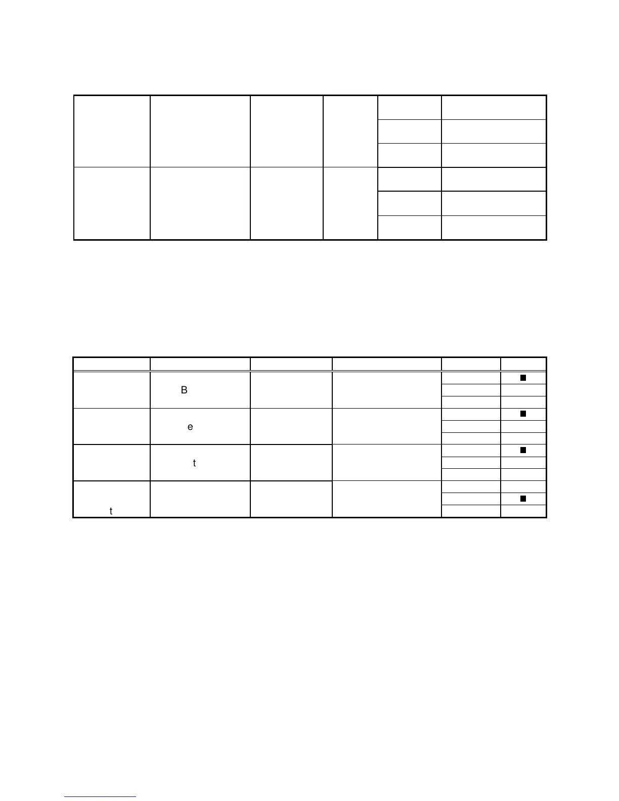
MagicBus Board LED Indicator Table, 2/2
LED 3 Off Not In Use
UART / USB
Mode
Right Center, Near
DIP Switch S1
Indicator Green On Faulty MagicBus
Board
Blinking With 5 & 4: UART;
Individually: USB
LED 1 Off No Power
Power to
MagicBus
Center, Near
Fuse F2
Indicator Red On Power Present
Board Blinking Intermittent Power
MagicBus Interface Connector & Jumper Table
Jumper Location Function Meaning Setting Default
JP 1 Upper Right Blue High Impedance Open
Between Video Low Impedance 1 & 2
(Note 1) JP4 and JP2 Impedance High Impedance 2 & 3
JP 2 Upper Right Green High Impedance Open
Between Video Low Impedance 1 & 2
JP1 & JP3 Impedance High Impedance 2 & 3
JP 3 Upper Right Red High Impedance Open
Between Video Low Impedance 1 & 2
(Note 3) JP2 & JP5 Impedance High Impedance 2 & 3
JP 4 Upper Right Video Positive Sync Open
Near Sync Negative Sync 1 & 2
(Note 3) JP1 & JP2 Polarity Positive Sync 2 & 3