Technical Information
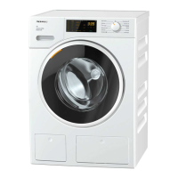
W1900 Series Clothes Washers
W1900 Series Clothes Washers – List of Figures
Figure 1-1: Appliance Overview (typical W1900 series washer).................................... 6
Figure 1-2: Overview of Controls (W1903 & W1918).....................................................7
Figure 1-3: Overview of Controls (W1926 & W1930).....................................................8
Figure 1-4: Overview of Controls (W1966)..................................................................... 9
Figure 1-5: Overview of Controls (W1986)................................................................... 10
Figure 1-6: 5 Kilogram Dispenser (W1903, W1918, W1930 & W1930i) ...................... 13
Figure 1-7: 6 Kilogram Dispenser (W1966 & 1986) ..................................................... 14
Figure 1-8: Overview of Components (W1903, W1918, W1930 & W1926) .................15
Figure 1-9: Overview of Components (W1966 & W1986)............................................ 16
Figure 2-1: Turning the left Shipping Strut counterclockwise.......................................19
Figure 2-2: Turning the right Shipping Strut clockwise................................................. 19
Figure 2-3: Removing the Strut Support Assembly......................................................20
Figure 2-4: Plugging the Shipping Strut Holes.............................................................20
Figure 2-5: Adjusting the legs to level the appliance.................................................... 21
Figure 4-1: Eco Wash System ..................................................................................... 26
Figure 4-2: Drum Suspension Components.................................................................27
Figure 4-3: Increased in water volume = increased pressure against the
Level Switch............................................................................................... 29
Figure 4-4: Dispenser Assembly..................................................................................30
Figure 4-5: Non-return valve ........................................................................................ 31
Figure 4-6: Main Motor Assembly ................................................................................ 32
Figure 4-7: Motor circuit ............................................................................................... 33
Figure 5-1: Removing the dispenser drawer ................................................................ 35
Figure 5-2: Service Access .......................................................................................... 36
Figure 5-3: Replacing the door seal............................................................................. 37
Figure 5-4: Air Trap and Level Switch Components .................................................... 38
Figure 5-5: Heater Element.......................................................................................... 39
Figure 5-6: Drain pump removal .................................................................................. 41
Figure 5-8: Removing Control Electronic ..................................................................... 43
Figure 5-9: Removing the Power electronic ................................................................. 44
Figure 5-10: Ribbon Cable with pin 1 position noted. .................................................... 45
Figure 5-11: Water level switch...................................................................................... 47
Figure 5-12: Heater relays with bracket .........................................................................48
4