OM-248965 Page 31
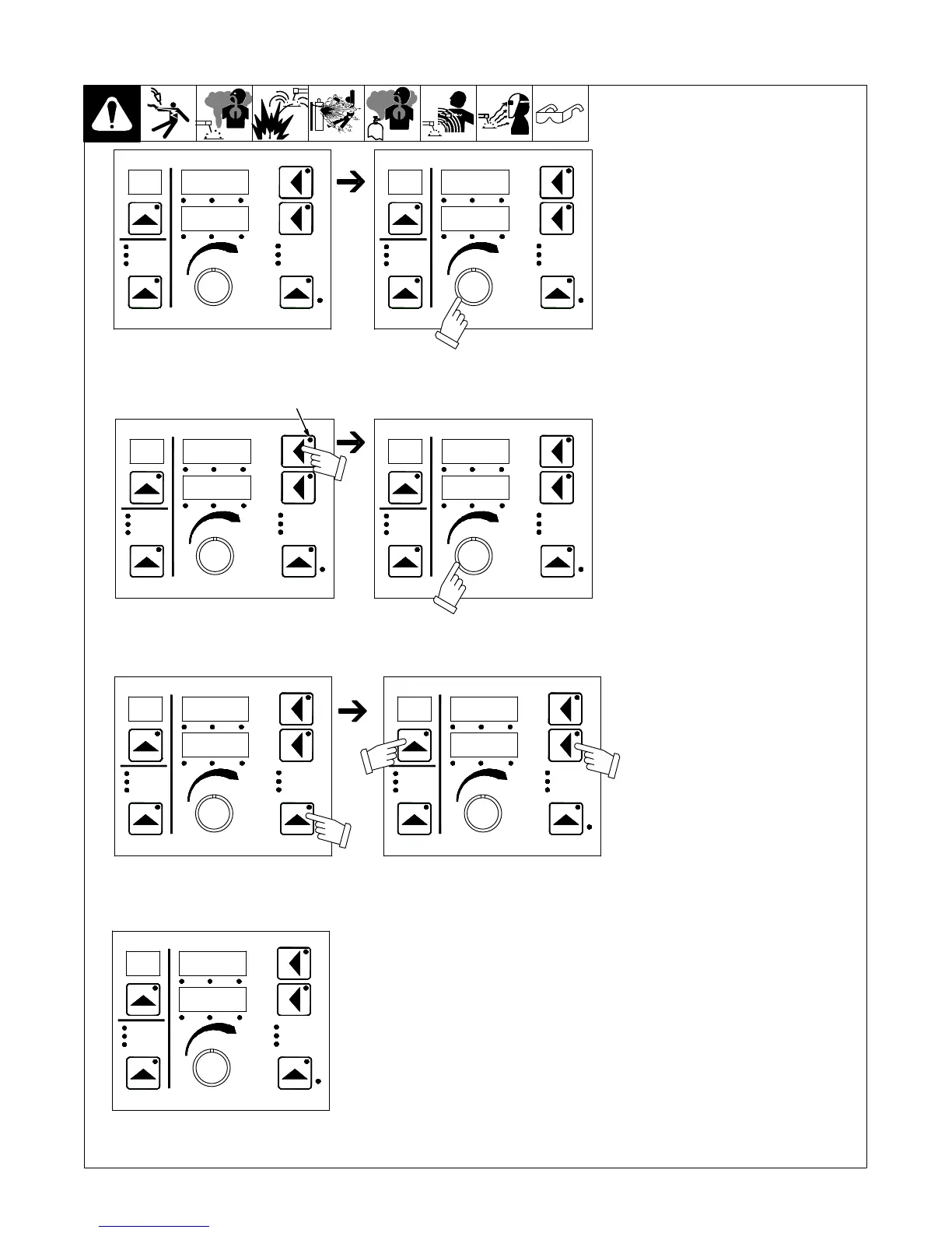
B. Software Revision
The top display shows the board
(PCM, UIM, and WFCM) and the
lower display shows the last 3 digits of
the circuit board part number plus a
letter designator.
After entering the user interface
menu, the initial display will vary by
the first item that appears.
Upper display push button LED
flashes to indicate this menu item
is available for selection. Press
the upper display push button.
SYS
RST
Trigger Control
Program
Process
Wire Type
Gas Type
Process Set up
Volts Time Arc Adjust
WFS Amps Arc Ctl
Sequence
Trigger Hold
Adjust Feeder Set Up
Trigger Control
Program
Process
Wire Type
Gas Type
Process Set up
Volts Time Arc Adjust
WFS Amps Arc Ctl
Sequence
Trigger Hold
Adjust Feeder Set Up
SW
REV
Trigger Control
Program
Process
Wire Type
Gas Type
Process Set up
Volts Time Arc Adjust
WFS Amps Arc Ctl
Sequence
Trigger Hold
Adjust Feeder Set Up
REV
SW
Rotate Adjust knob until Software
Revision (SW REV) appears on
the display.
Rotate Adjust knob to scroll
through the software revision for
each circuit board.
Trigger Control
Program
Process
Wire Type
Gas Type
Process Set up
Volts Time Arc Adjust
WFS Amps Arc Ctl
Sequence
Trigger Hold
Adjust Feeder Set Up
UIM
123A
LED
Unit goes back to its standby status.
PCM
321B
Trigger Control
Program
Process
Wire Type
Gas Type
Process Set up
Volts Time Arc Adjust
WFS Amps Arc Ctl
Sequence
Trigger Hold
Adjust Feeder Set Up
The Set Up push button LED flashes indicating
that pressing this button will exit the user
interface menu. Press the Set Up push button.
Trigger Control
Program
Process
Wire Type
Gas Type
Process Set up
Volts Time Arc Adjust
WFS Amps Arc Ctl
Sequence
Trigger Hold
Adjust Feeder Set Up
25
200
1
PCM
321B
Trigger Control
Program
Process
Wire Type
Gas Type
Process Set up
Volts Time Arc Adjust
WFS Amps Arc Ctl
Sequence
Trigger Hold
Adjust Feeder Set Up
To exit the user interface menu, momentarily
press the Program push button and lower
display push button at the same time.