OM-260430 Page 30
F
This server page IP address (169.254.0.2) is the factory default for the Insight module. If you plan to set the Insight device connectivity to
use static IP address in your company, this server page IP address will change permanently once you assign the static IP in the process
below..
F
Using a static IP address connection enables you to view the server page of any Insight device installed on the shop floor from anywhere
on your network by browsing to its static IP address.
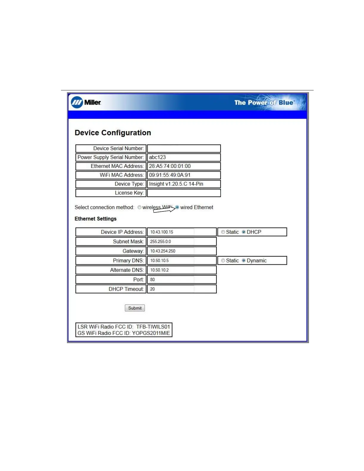
In the Ethernet Settings section, select Static for Device IP Address and Primary DNS.
Insert the device IP static address, subnet mask, gateway, DNS information, and port number provided by your IT Department (see Figure 4-21).
When finished, click Submit to save your settings for this device.
OM-286673 Page 28
6. On the server page, select the radio button labeled Wired Ethernet and enter the desired parameters based on your company’s network environ-
ment as defined on the Insight Network Connectivity Requirements Checklist responses (see Section 4-7).
. This server page IP address (169.254.0.2) is the factory default for the Insight module. If you plan to set the Insight device connectivity to use
static IP address in your company, this server page IP address will change permanently once you assign the static IP in the process below.
. Using a static IP address connection enables you to view the server page of any Insight device installed on the shop floor from anywhere on your
network by browsing to its static IP address.
a. In the Ethernet Settings section, select Static for Device IP Address and Primary DNS.
b. Insert the device IP static address, subnet mask, gateway, DNS information, and port number provided by your IT Department (see
Figure 4-24).
MC10001Z
AC1000000X1X1X00XX00X0
Figure 4-24. Insight Server Page
c. When finished, click Submit to save your settings for this device.
7. Unplug the Ethernet (CAT5 or CAT6) patch cord from your PC, and connect the Insight module to your corporate Ethernet network jack using the
patch cord.
8. Turn the welding power source off, and remove any USB stick if still inserted.
9. Wait 10 seconds.
10. Turn welding power source on. The yellow Network light should turn on first when it identifies your network. The green Internet light should turn on
when it sees open access to the Internet.
11. When both LED lights are illuminated solid, the physical installation for Static IP Address is complete.
. If the LEDs are not illuminated and the network connection has been verified (See Section 4-11), please contact your Miller Sales representative.
. To continue with firmware installation, proceed to Section 4-13.
Figure 4-21. Insight Server Page
7. Unplug the Ethernet (CAT5 or CAT6) patch cord from your PC, and connect the Insight module to your corporate Ethernet network jack using
the patch cord.
8. Turn the welding power source off and remove any USB stick if still inserted.
9. Wait ten seconds.
10.Turn welding power source on. The yellow Network light should turn on first when it identifies your network. The green Internet light should
turn on when it sees open access to the Internet.
11. When both LEDs are illuminated solid, the physical installation for Static IP Address is complete.
F
If the LEDs are not illuminated and the network connection has been verified (See Section 4-6), please contact your Miller Sales
representative.
F
To continue with firmware installation, proceed to Section 4-8.
 Loading...