7
Outdoor Installations
The XT and XW pump is designed as a totally
enclosed unit suitable for installation either indoors
or outdoors. However, for outdoor installations the
pump mounting area should be selected to provide
protection against environmental extremes:
A. Operation with continuous exposure to tropical
or subtropical sunshine with ambient tempera-
tures above 90°F (32°C), which would cause
higher oil temperatures and affect lubricity
should be avoided. Good installation practice
would dictate providing a sun shade cover over
the pump with open sides to obtain the best air
circulation around the pump.
B. Frequent start-up where the pump has been
idle in an ambient temperature below 30°F (-
1°C) is not recommended. Provide a remov-
able, insulated enclosure over the pump and
mounting base with provisions for an electrical
heater (100 watt light, heat lamp, heater tape
etc.) to maintain the pump oil temperature
above 30°F (-1°C).
2.5 MOTOR MOUNTING: DIRECT MOUNTED
AND API FLANGED MOUNTED
Direct mounted motors have an extended shaft
with worm gear and bearing attached (Figure 9).
If an API flange mounted motor option was
selected for the XT / XW pump, a factory or cus-
tomer supplied motor mounts to the API flange,
using a coupling (Figure 10).
2.6 ELECTRICAL CONNECTIONS
Check to be sure that the electrical supply matches
the pump motor nameplate electrical characteris-
tics. Motor rotation must be counter clockwise
when viewed from the top end of the motor.
ON SINGLE-PHASE PUMP MOTORS
THE ROTATION WILL BE DETERMINED
AT THE FACTORY AND MUST NOT BE
CHANGED. ON THREE-PHASE PUMP
MOTORS THE ROTATION MUST BE
DETERMINED AT THE TIME OF INSTAL-
LATION AND PRIOR TO START-UP.
OPERATION WITH THE WRONG ROTA-
TION WILL DAMAGE THE PUMP AND
MOTOR AND VOID THE WARRANTY.
SHAFT ROTATION CAN BE OBSERVED
BY REMOVING THE COVER PLATE
OVER THE ELECTRICAL CONNEC-
TIONS.
2.7 MOTORS
Adequate power is provided to the simplex XT
pump by the standard 1/2 HP (0.37 KW) motor
(XW pump by the standard 1 HP (0.75 KW) or 1.5
HP (1.1 KW) motor.) The motor is normally a totally
enclosed non-ventilated, type, which is mounted on
a 56C face flange or IEC Frame 71 flange. The
gear reducer (worm shaft) fits onto the standard
motor without using a coupling.
The normal temperature rise for these motors is
50°C above ambient temperature, and it can be
expected that these motors will appear to operate
at higher temperatures than are normally experi-
enced. However, there is no cause for worry if the
following precautions are observed:
A. The motor is placed where there is adequate
ventilation and is protected against excessive
radiation from steam pipes and other heat
sources.
B. The overload heater in the starting device
should be correctly sized for motor full load
current rating as shown on the motor data
plate.
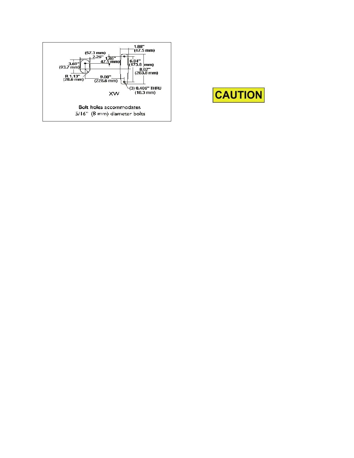
Figure 4. XW Bolt Hole Dimensions