— 1.25 —
Setting the response value with respect to the valid area
[MODE SET] > [OH UNIT]
The response value that is to be transmitted to the CAD in response to a valid area coordinate output
command for the device is selected between the following.
Set values
INITIAL VALUE: The value of the max. valid cutting area of the device is transmitted to
CAD.
SET VALUE: The value set in the “Setting the cutting area” on the LOCAL MENU.
(See page 2.43).
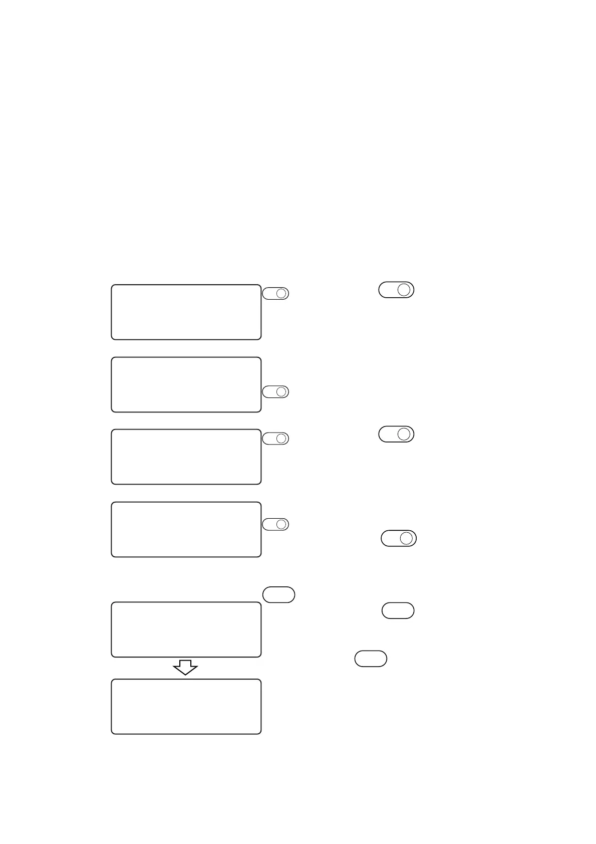
1 Press the
PAGE
+
key several times
until the LCD indicates page 3 of the
LOCAL MENU.
2 Select the [MODE SET].
3 Press the
PAGE
+
key several times
until the LCD indicates page 4 of the
[MODE SET].
4 Set the [OH UNIT] to one of the fol-
lowing.
Press the
F1
+
key to change the se-
lected item alternately.
INITIAL VALUE, SET VALUE
5 Enter the input values.
Press the
END
key to enter the input
values.
If you do not enter the input data, press
the
C E
key.
[ LOCAL ] 1 / 4
TOOL SELECT ———>
CONDITION ———>
TEST CUT ———>
[ LOCAL ] 3 / 4
INTERFACE ———>
MODE SET ———>
SELF TEST ———>
< MODE SET > 1 / 5
Z STROKE ∗7mm >
MULTI–PASS ——— >
VACUUM ∗AutoOFF>
< MODE SET > 4 / 5
OH UNIT ∗INIT val >
ORIGIN ∗CENTER >
GDP ∗0.025 mm >
< MODE SET > 4 / 5
OH UNIT SET val >
ORIGIN ∗CENTER >
GDP ∗0.025 mm >
END
[ LOCAL ] 3 / 4
INTERFACE ———>
MODE SET ———>
SELF TEST ———>
F1
+
F2
+
PAGE
+
PAGE
+
 Loading...


