6-26 BeneVision N17/BeneVision N15/BeneVision N12 Patient Monitor Service Manual
2. Removing the rear case of module rack
As shown in the following figure, use a tweezer to take out the six screw covers on the rear case.
Loosen and remove the six M3X16 cross recessed pan head screws, and separate the front case from
the rear case.
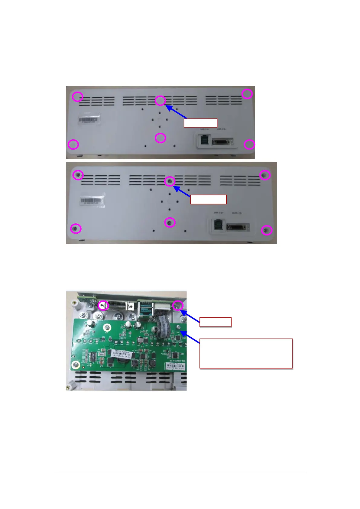
3. Removing the module rack interface board
Loosen and remove the two M3X8 cross recessed pan head screws, disconnect the cable between the
interface board and the internal module rack COMM board, and then remove the interface board.
Screw cover
M3X16 screw
M3X8 screw
Cable from the interface board of
external module rack to the 8-slot board