BeneVision N22/BeneVision N19 Patient Monitor Service Manual 2-5
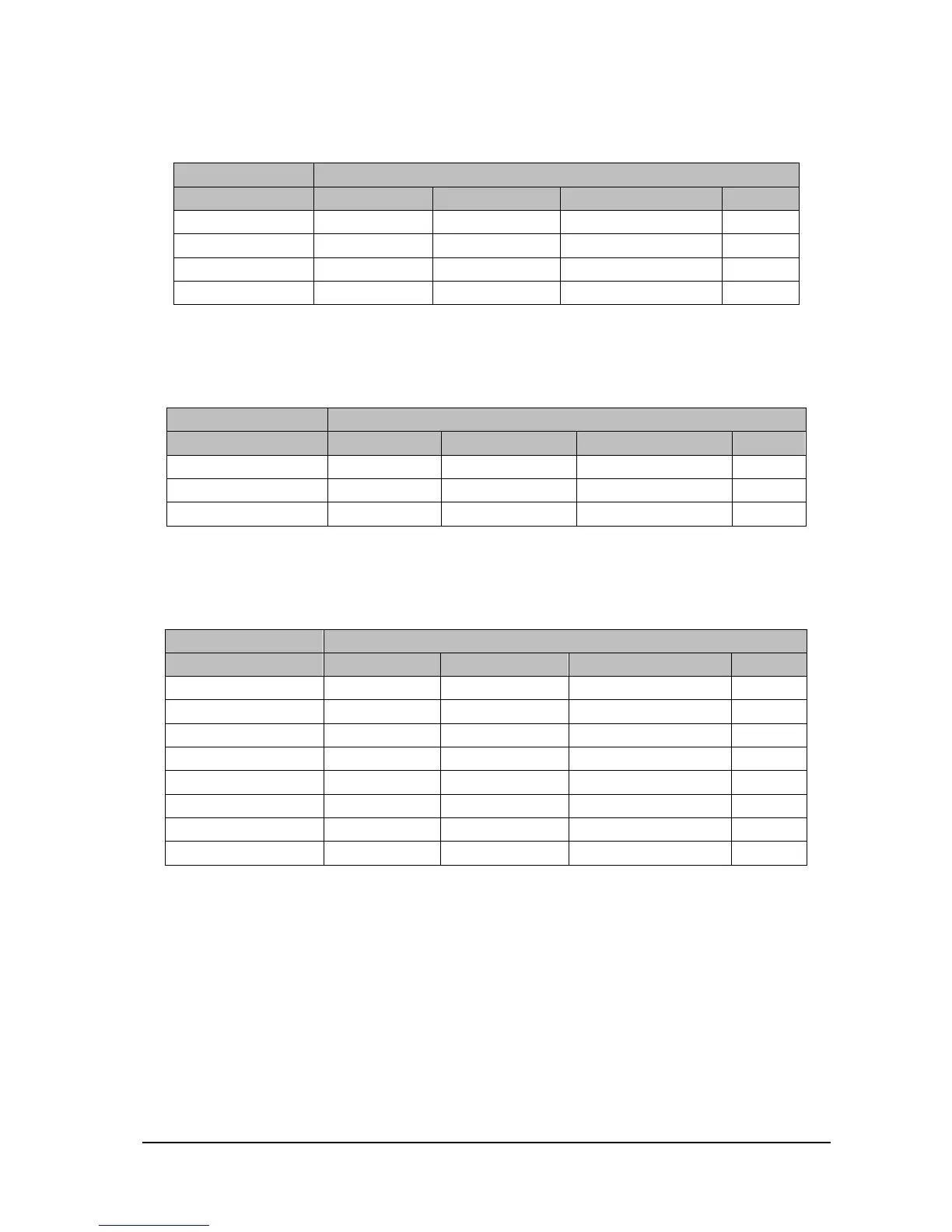
Power connector of the battery interface board
Used for connecting the charging and discharging power of the battery interface board.
Connector Type B4PS-VH
Pin No. Signal Name Signal Direction Function Definition Remarks
1 GND / Ground /
2 BAT BI Battery power /
3 BAT BI Battery power /
4 GND / Ground /
Signal connector of the battery interface board
Used for connecting the battery availability signal and SMB signal of the battery interface board.
Connector Type B3B-PH-K-S
Pin No. Signal Name Signal Direction Function Definition Remarks
1 BAT_BC IN Battery availability signal /
2 SMB_D BI SMBus data signal /
3 SMB_C OUT SMBus clock signal /
Power connector of the main board
Used for connecting the main board to provide 3.3V, 5V and 16V DC power to the main board.
Connector Type 43045-0800
Pin No. Signal Name Signal Direction Function Definition Remarks
1 3.3V OUT DC output /
2 5V OUT DC output /
3 5V OUT DC output /
4 16V OUT DC output /
5 GND / Ground /
6 GND / Ground /
7 GND / Ground /
8 GND / Ground /
 Loading...