2-8 BeneVision N22/BeneVision N19 Patient Monitor Service Manual
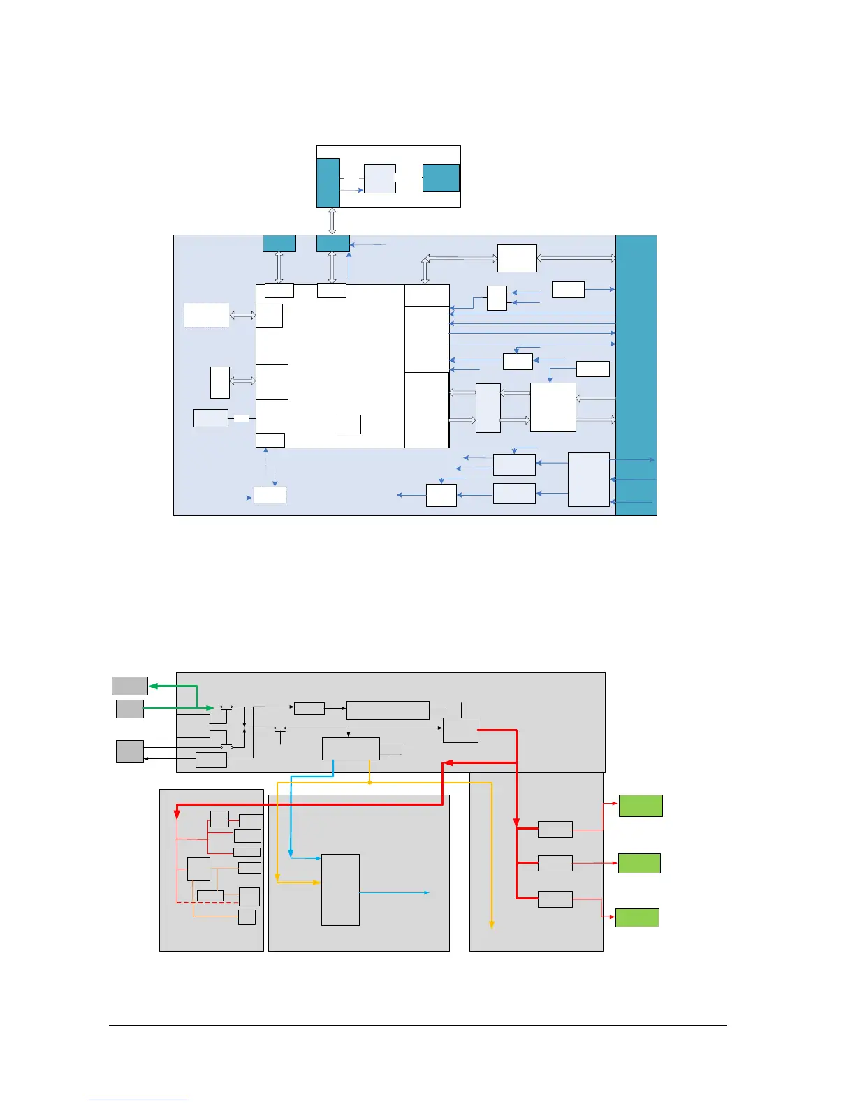
2.2.5 iView Substrate
iView substrate is mainly used to carry the COME module (COM Express module), extending the function of the COME to
standard interfaces as well as communication signals with the main board.
��5V
iPC support board
COME Type10
i
P
C
C
o
n
n
RJ45
m
S
A
T
A
SATA0
Conn
GbE
USB0
UART
0
HDMI
TMDS
HDMI to
MIPI-CSI2
CSI2 x4 Lane
16V
Power
Managment
PWR_BTN#
RST#
FAN
FAN
Control
FAN
Contro
l
5VCC
5VSB
Power
Switch
16V_iPC
SUS_S4#
16V Over
Current
Protection
3.3V DC-DC
5V DC-DC
Always on
VDD
5VSB
Power
Switch
SUS_S3#
5VCC
BD_16V
SUS_S3#
16V
SUS_S3#
BD_16V_OC#
BD_16V_EN
iPC_BC#
Connect
to GND
PCIe Port0
PCIe
GbE
MAC
/PHY
(I211-AT)
GbE
Debug
� Reserved�
TPM
Level
Shifter
TMDS
DDC
DDC
I2C
EEPROM
EDID
5VSB
16V
VDD_PG
&
0
0
0
SUS_S3#
VDD_PG
SUS_S3#
PWR_OK
Conn
USB Type A
Connector x
4
USB Hub
(USB2517
)
USB x 4
USB
CB_RST
#(COME)
RST#
BEEP
SPKR
The COME module uses Type10 module (mechanical size: 55 mm x 84 mm) as defined in the specifications, and the
connection with the main board could be realized with one 220pin socket.
2.3 Power System
2.3.1 Power Diagram of the Main Unit and the Module Rack
LCD
backlight
Alarm LED
board
USB
12V
12V
12V
LCD
5V
5V
CPU
CPU of
main
control
5V@5
.2A
3.3V
Main board
Display interface board
Slow
start
power
Slow start
power
Power
Supply
DCDC
5V
3.3V
3
.3VLDO
MCU� M0�
12V
_EN
5
V_EN
3
.3V
_EN
DCDC board
4mA(Typ)
AC-
DC
board
Charging and
discharging
management
LED
DCDC
12V
12V
3.3V
VBUS
_EN
Charging
circuit
3.3V
Hot swap
circuit
Hot swap
circuit
Hot swap
circuit
Module rack1
Module rack3
12
V
12V
VBUS:
10V-
16V/140W(MAX)
16
V
iView module
12V
12V
EN
12V
12V
Module rack2
12V
12V
DCDC board
The power management MCU is the core of the power management. In the system, 3.3V STB output could be realized
with any power input (AC or battery), which means that the power management MCU works properly. The display
interface board and module rack of the front housing could directly use the system's 12V power supply.
 Loading...