6-6 6 Hardware
Switching pumps and valves to control the flow of liquid.
Detecting the level of liquid and obstruction signal.
Detecting the signal of position sensors.
Controlling the heater for heating.
Detecting the signal of the water surface.
Controlling the ISE module.
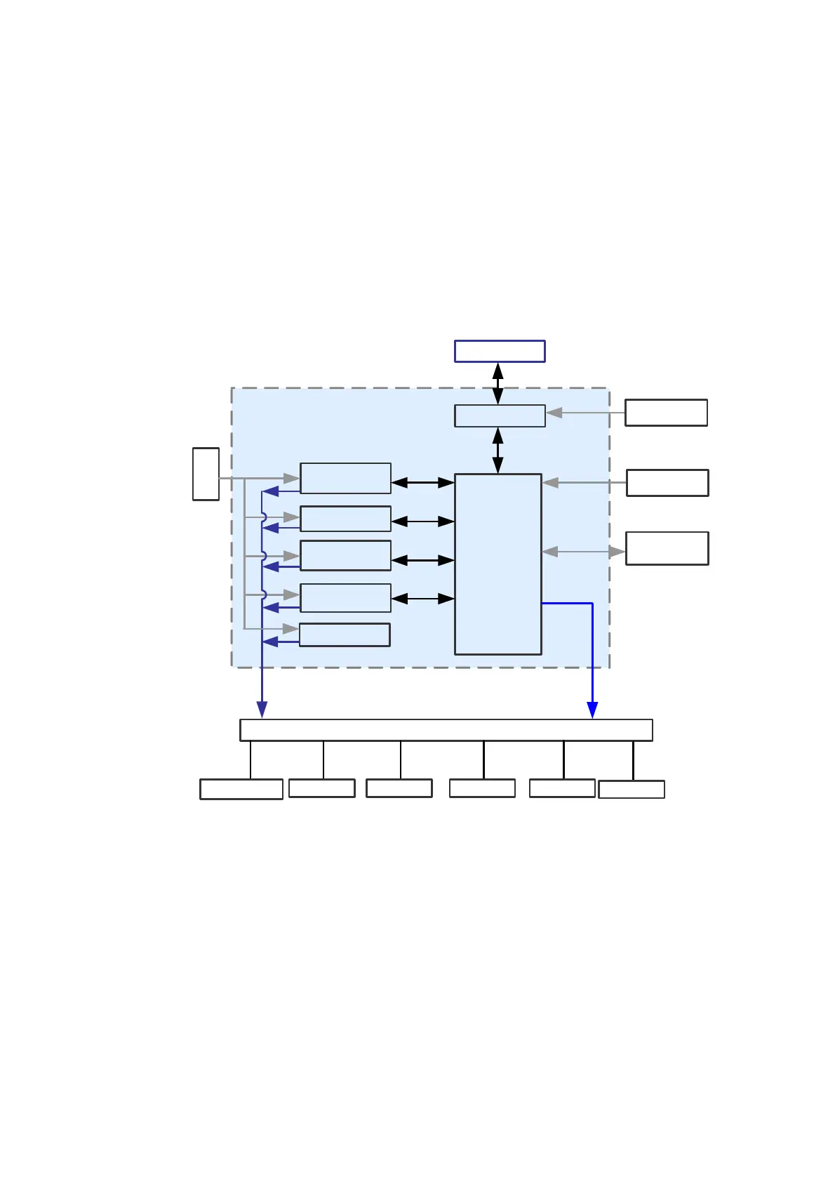
Figure 6-3 shows the function framework of the main board.
Figure 6-3 Function of the Main Board
Main Unit
Sample probe
Unit
Temperature
Control Unit
Reaction Disk
Unit
Auto Washing
Unit
FPGA
BUS
BUS
BUS
BUS
Bus
Sensor
s
PC
? ?
Sensors
Driving Module
Step Motor
Heator Relay Pump Valve
Module of
ISE
Sensors
Control Moule
Mixing Unit
Control
Signal
Control
Signal
DC motor
6.6.3 Drive Board
The drive board is to receive the control signals from the main control board and control
the drive components, such as the reaction disk, the reagent\sample disk, the sampling
probe, the mixer and the filter wheel. It also controls the switches of two pumps, the valves,
the lamp and the temperature controlling system. The detaied functions are:
Controlling the movement components
Controlling the pumps and the valves
Controlling lamp
Controlling heater
Figure 6-4 shows the function framework of the drive board.