4 Units Description
4-22
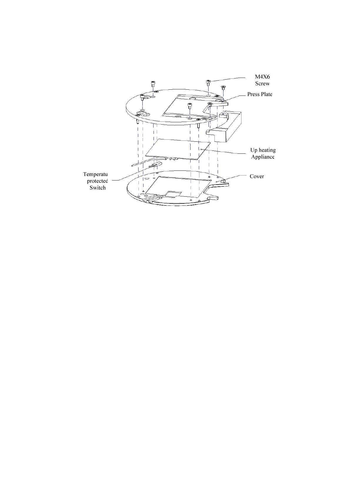
4.4.3.4 Cover Assembly
Figure 4-24 Cover Assembly
The temperature protective switch and up-heating appliance are installed between the press
plate and the cover, and they can be removed by loosening four M4x6 hexagon socket head
screws.
Precautions:
1. The side of up-heating appliance that is incontact with the press plate must be coated
with heat –conducting glue (0.1-0.2mm thick), and the up-heating appliance cables are
placed in the groove of the press plate so as to avoid pressure.
2. The temperature protective switch must be coated with heat-conducting glue
(0.1-0.2mm thick), and it should be carefully installed in the specified position while
installing.
4.5 Mixing Unit
4.5.1 Function Introduction
The mixing unit is equipped with a mixing bar, which is used to stir the liquid in cuvettes.
Additionally, the mixing unit has a specified mechanical position and is able to lock itselt
when power failure occurs.
The working position of the mixing bar: the wash well and the stirring position
4.5.2 Components of Mixing Unit
The mixing unit consists of mixing drive assembly and mixing arm assembly.