System Overview 2-19
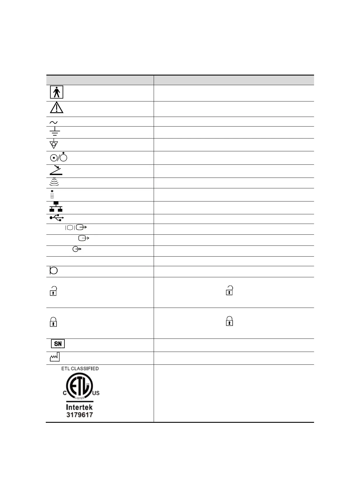
2.11 Symbols
This system uses the symbols listed in the following table. Their meanings are explained as follows:
Type-BF applied part
Caution
Equipotentiality
Power button
Foot switch
Pencil probe port
Network port
S-VIDEO
Reserved, used for separate video output
AUDIO
Used for stereo audio output.
High definition multimedia interface.
When the lever located at the bottom of the monitor
supporting arm points to , you can move the monitor
to the right and left.
When the lever located at the bottom of the monitor
supporting arm points to , the supporting arm is fixed
in the middle position.
Product serial number
Manufacture date
CONFORMS TO AAMI STD ES 60601-1, IEC STD
60601-1-6, 60601-2-37
CERTIFIED TO CSA STD C22.2 NO. 60601-1, NO.
60601-1-6, NO. 60601-2-37