12-24 Probes and Biopsy
3
guided bracket
Used for installing the needle-guided bracket on the
transducer
4
Knob of fixing
needle-guided
bracket
Used for fixing the needle-guided bracket on the transducer
5
Specification of
guiding block (13G)
Matched with the corresponding biopsy needle (13G)
6
Knob of fixing the
guiding block
Used for fixing the guiding block
7 Needle guide angle The needle guide angle of this needle-guided bracket
8
needle-guided
bracket
Matched with the tabs of the transducer
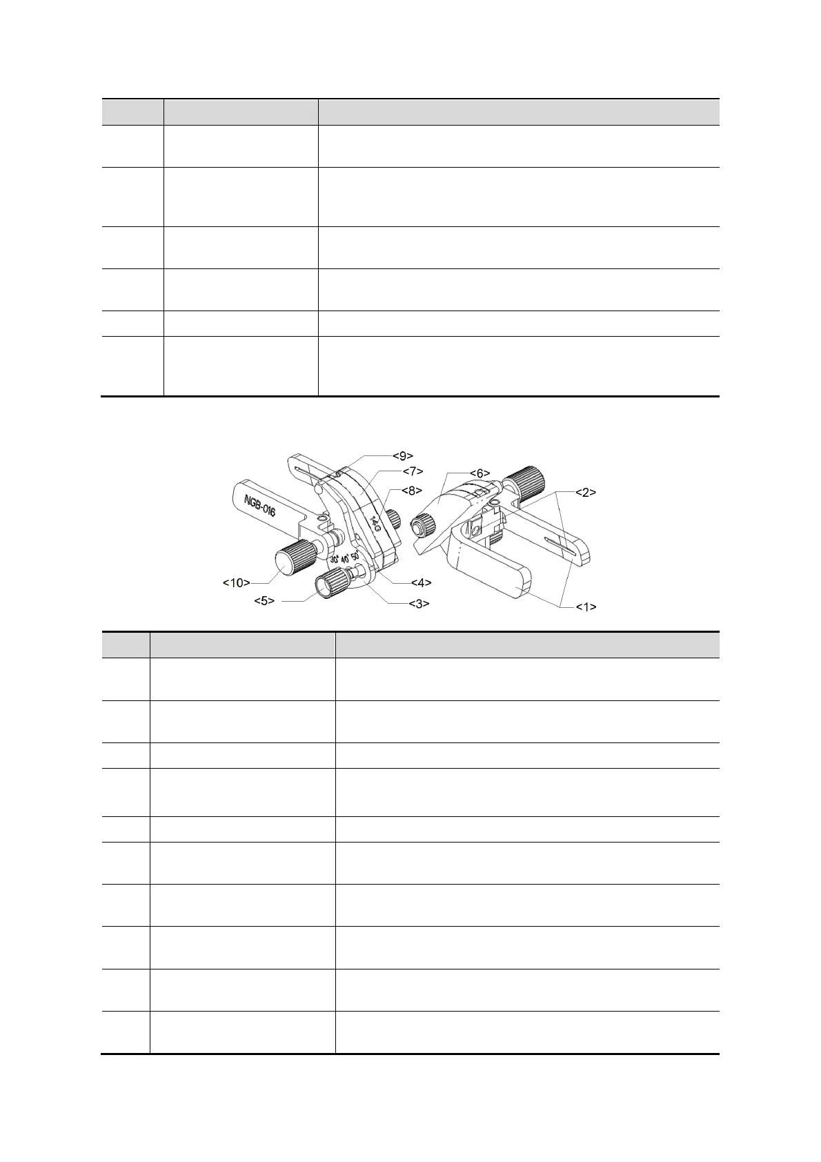
NGB-016
<1>
bracket
Used for installing the needle-guided bracket on the
transducer.
<2>
Groove of the needle-
guided bracket
Matches with the tab of the transducer.
<3> Angle adjusting base There are 3 types of angles available to be adjusted.
<4>
Angle shift sign (30°, 40°,
50°)
Matches with the biopsy angle
(30°, 40°, 50°).
<5> Angle pinch nut Used for fixing the angle lock at a chosen angle.
<6> Angle block
Determines the angle of the biopsy; different
specifications of blocks can be used.
<7> Guiding block
Used for installing the needles of different specifications,
5 types of needles are available.
<8>
Specification of guiding
block (14G)
Matched with the corresponding biopsy needle (14G).
<9>
needle
Used for installing the needles.
<10>
guided bracket
Used for locking the needle-guided bracket and the
transducer.