Parameter Menus Operations
2 - 16 0070-10-0666-01 Trio™ Operating Instructions
2.4.1.3 Lead Placement
The computerized arrhythmia algorithm works best when the patient’s R wave is significantly
larger than the P wave or the T wave. If the R wave is not significantly larger than other lower
voltage waves on the ECG tracing, the computer may have some difficulty in identifying the
appropriate waves. On some patients, electrode patch placement and/or the viewed ECG
lead may need to be adjusted in order to obtain a significant R wave.
This section outlines lead placement according to the guidelines of the American Heart
Association (AHA) and the International Electro-Technical Commission (IEC).
Standard 3-wire Lead Sets
Standard 3-wire lead sets include 3 ECG leads (I, II and III). Only 1 lead is monitored.
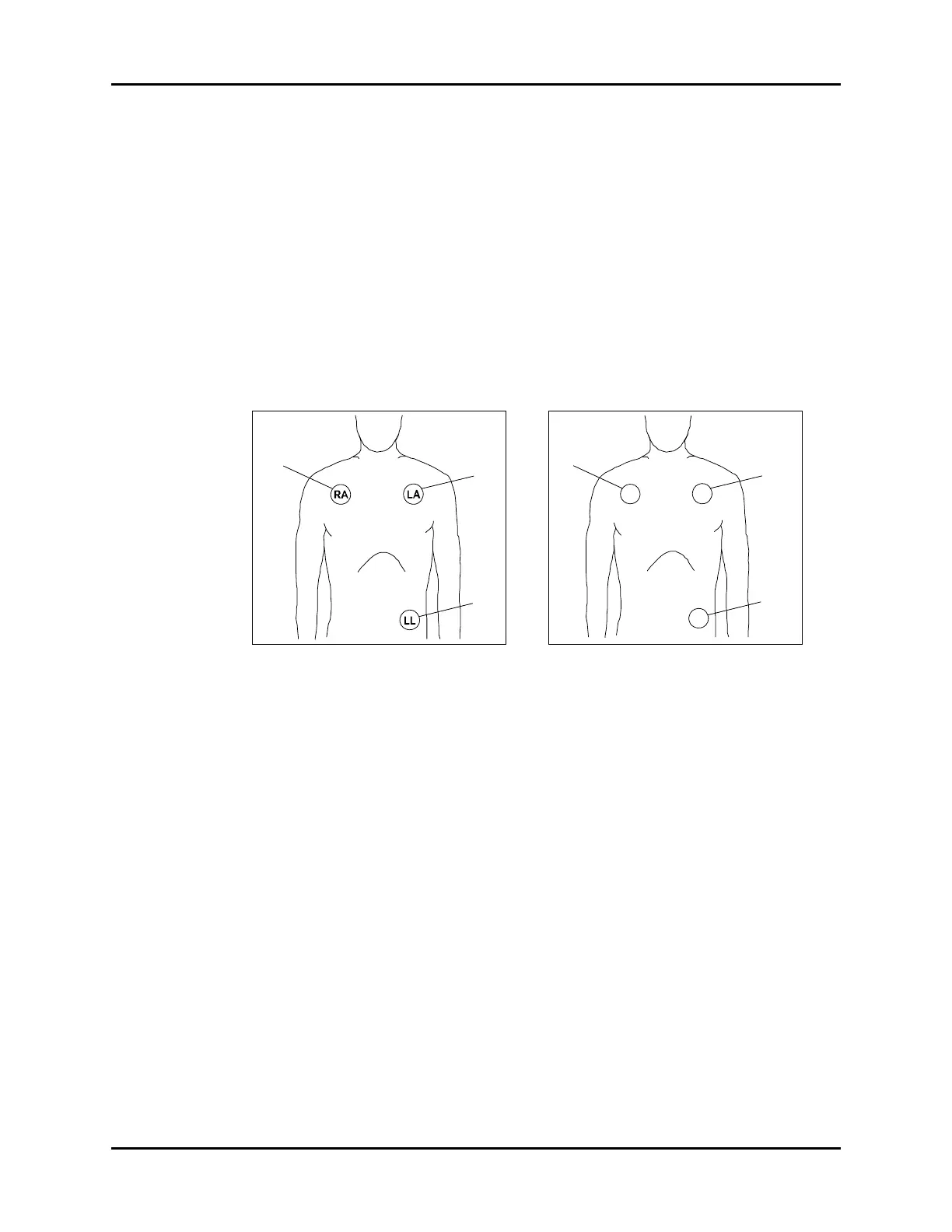
FIGURE 2-14 3-wire Lead Placement
(AHA)
FIGURE 2-15 3-wire Lead Placement
(IEC)
• Place the RA (white) electrode under the
patient’s right clavicle, at the mid-
clavicular line within the rib cage frame.
• Place the LA (black) electrode under the
patient’s left clavicle, at the mid-
clavicular line within the rib cage frame.
• Place the LL (red) electrode on the
patient’s lower left abdomen within the
rib cage frame.
• Place the R (red) electrode under the
patient’s right clavicle, at the mid-
clavicular line within the rib cage frame.
• Place the L (yellow) electrode under the
patient’s left clavicle, at the mid-
clavicular line within the rib cage frame.
• Place the F (green) electrode on the
patient’s lower left abdomen within the
rib cage frame.
 Loading...