(2720)A 17
12231223
12231223
1223
G G-114G G-114
G G-114G G-114
G G-114
G G-114G G-114
G G-114G G-114
G G-114
PinkPink
PinkPink
Pink
BlueBlue
BlueBlue
Blue
GrayGray
GrayGray
Gray
GrayGray
GrayGray
Gray
WhiteWhite
WhiteWhite
White
2766-16042766-1604
2766-16042766-1604
2766-1604
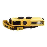
7. Apply G-114 to the directed part of the cover bottom strobo. 7. Apply G-114 to the directed part of the cover bottom strobo.
7. Apply G-114 to the directed part of the cover bottom strobo. 7. Apply G-114 to the directed part of the cover bottom strobo.
7. Apply G-114 to the directed part of the cover bottom strobo.
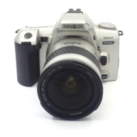
8. Solder the lead wire to the compl reflector.8. Solder the lead wire to the compl reflector.
8. Solder the lead wire to the compl reflector.8. Solder the lead wire to the compl reflector.
8. Solder the lead wire to the compl reflector.
Compl reflectorCompl reflector
Compl reflectorCompl reflector
Compl reflector
Cover bottom stroboCover bottom strobo
Cover bottom stroboCover bottom strobo
Cover bottom strobo
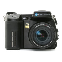
9. Assemble 2766-1604 in the direction of the figure. 9. Assemble 2766-1604 in the direction of the figure.
9. Assemble 2766-1604 in the direction of the figure. 9. Assemble 2766-1604 in the direction of the figure.
9. Assemble 2766-1604 in the direction of the figure.
10. Arrange the lead wire.10. Arrange the lead wire.
10. Arrange the lead wire.10. Arrange the lead wire.
10. Arrange the lead wire.
NotchNotch
NotchNotch
Notch
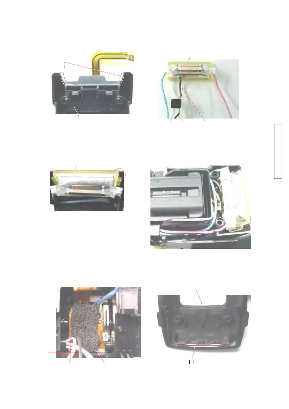
11. Stick 1223 onto the position of the figure. 11. Stick 1223 onto the position of the figure.
11. Stick 1223 onto the position of the figure. 11. Stick 1223 onto the position of the figure.
11. Stick 1223 onto the position of the figure.
12. Apply G-114 to the directed part of the cover top strobo.12. Apply G-114 to the directed part of the cover top strobo.
12. Apply G-114 to the directed part of the cover top strobo.12. Apply G-114 to the directed part of the cover top strobo.
12. Apply G-114 to the directed part of the cover top strobo.
Cover top stroboCover top strobo
Cover top stroboCover top strobo
Cover top strobo
Taper partTaper part
Taper partTaper part
Taper part