(2720)A 5
2782-12962782-1296
2782-12962782-1296
2782-1296
2782-12982782-1298
2782-12982782-1298
2782-1298
04930493
04930493
0493
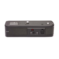
Fig. 1 Installation of the cabinet sideFig. 1 Installation of the cabinet side
Fig. 1 Installation of the cabinet sideFig. 1 Installation of the cabinet side
Fig. 1 Installation of the cabinet side
1. Arrange the FPC of the cabinet side as shown on the figure.1. Arrange the FPC of the cabinet side as shown on the figure.
1. Arrange the FPC of the cabinet side as shown on the figure.1. Arrange the FPC of the cabinet side as shown on the figure.
1. Arrange the FPC of the cabinet side as shown on the figure.
2. Stick 2782-1296 as shown on the figure to prevent the FPC of the cabinet side from unstableness.2. Stick 2782-1296 as shown on the figure to prevent the FPC of the cabinet side from unstableness.
2. Stick 2782-1296 as shown on the figure to prevent the FPC of the cabinet side from unstableness.2. Stick 2782-1296 as shown on the figure to prevent the FPC of the cabinet side from unstableness.
2. Stick 2782-1296 as shown on the figure to prevent the FPC of the cabinet side from unstableness.
FPC of the cabinet sideFPC of the cabinet side
FPC of the cabinet sideFPC of the cabinet side
FPC of the cabinet side
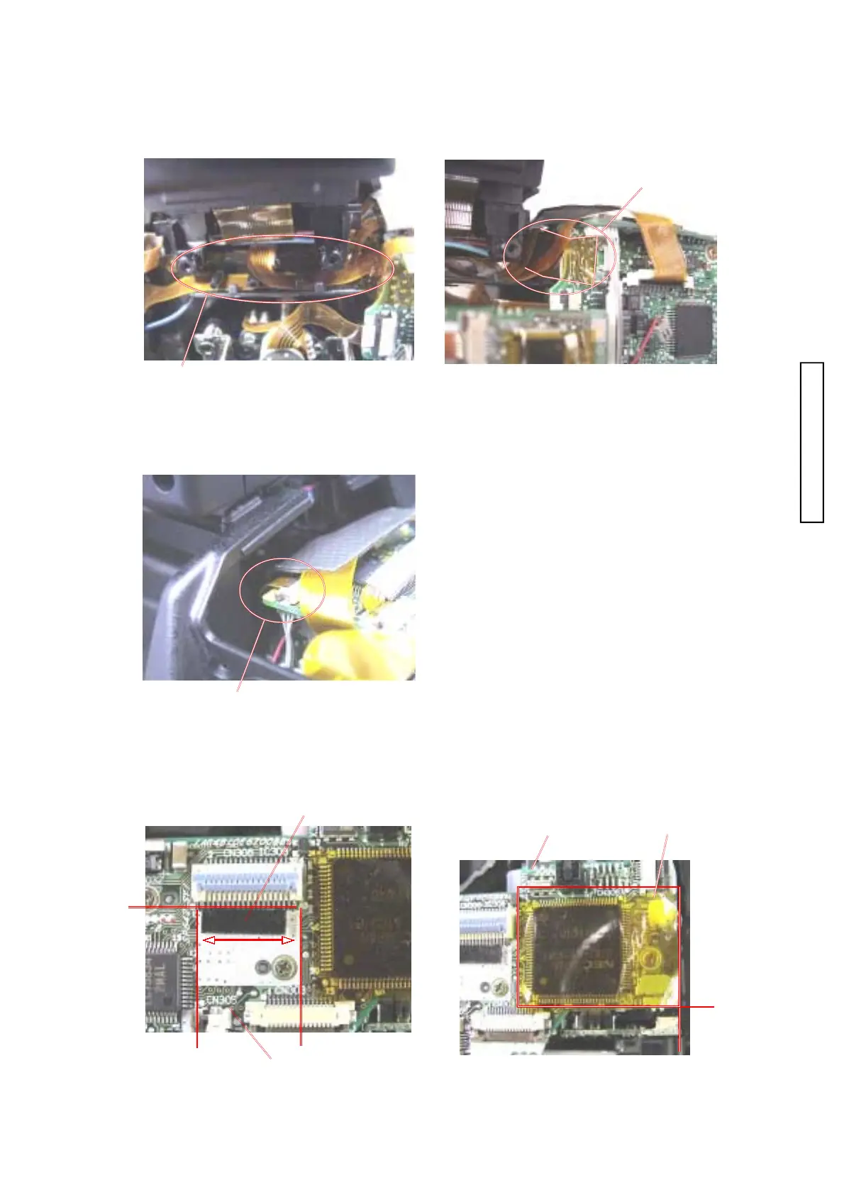
Fig. 2 Installation of the assy, cabi backFig. 2 Installation of the assy, cabi back
Fig. 2 Installation of the assy, cabi backFig. 2 Installation of the assy, cabi back
Fig. 2 Installation of the assy, cabi back
Install the assy cabi back with a care of the FPC ofInstall the assy cabi back with a care of the FPC of
Install the assy cabi back with a care of the FPC ofInstall the assy cabi back with a care of the FPC of
Install the assy cabi back with a care of the FPC of
the cabinet side.the cabinet side.
the cabinet side.the cabinet side.
the cabinet side.
FPC of the cabinet sideFPC of the cabinet side
FPC of the cabinet sideFPC of the cabinet side
FPC of the cabinet side
Compl PWB SY-1Compl PWB SY-1
Compl PWB SY-1Compl PWB SY-1
Compl PWB SY-1
Fig.3 Installation of the Cabinet topFig.3 Installation of the Cabinet top
Fig.3 Installation of the Cabinet topFig.3 Installation of the Cabinet top
Fig.3 Installation of the Cabinet top
1. Stick 0493 and 2782-1163 at the points on the figure. 1. Stick 0493 and 2782-1163 at the points on the figure.
1. Stick 0493 and 2782-1163 at the points on the figure. 1. Stick 0493 and 2782-1163 at the points on the figure.
1. Stick 0493 and 2782-1163 at the points on the figure.
Compl PWB SY-1Compl PWB SY-1
Compl PWB SY-1Compl PWB SY-1
Compl PWB SY-1