6 (2720)A
REPAIR GUIDE
B B-10B B-10
B B-10B B-10
B B-10
2782-11632782-1163
2782-11632782-1163
2782-1163
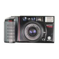
2. Stick 2782- 1163 at the points on the figure. 2. Stick 2782- 1163 at the points on the figure.
2. Stick 2782- 1163 at the points on the figure. 2. Stick 2782- 1163 at the points on the figure.
2. Stick 2782- 1163 at the points on the figure.
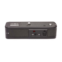
3. Arrange the harness as shown on the figure to install the cabinet top. 3. Arrange the harness as shown on the figure to install the cabinet top.
3. Arrange the harness as shown on the figure to install the cabinet top. 3. Arrange the harness as shown on the figure to install the cabinet top.
3. Arrange the harness as shown on the figure to install the cabinet top.
Fig.4 Assembly of the cabinet sideFig.4 Assembly of the cabinet side
Fig.4 Assembly of the cabinet sideFig.4 Assembly of the cabinet side
Fig.4 Assembly of the cabinet side
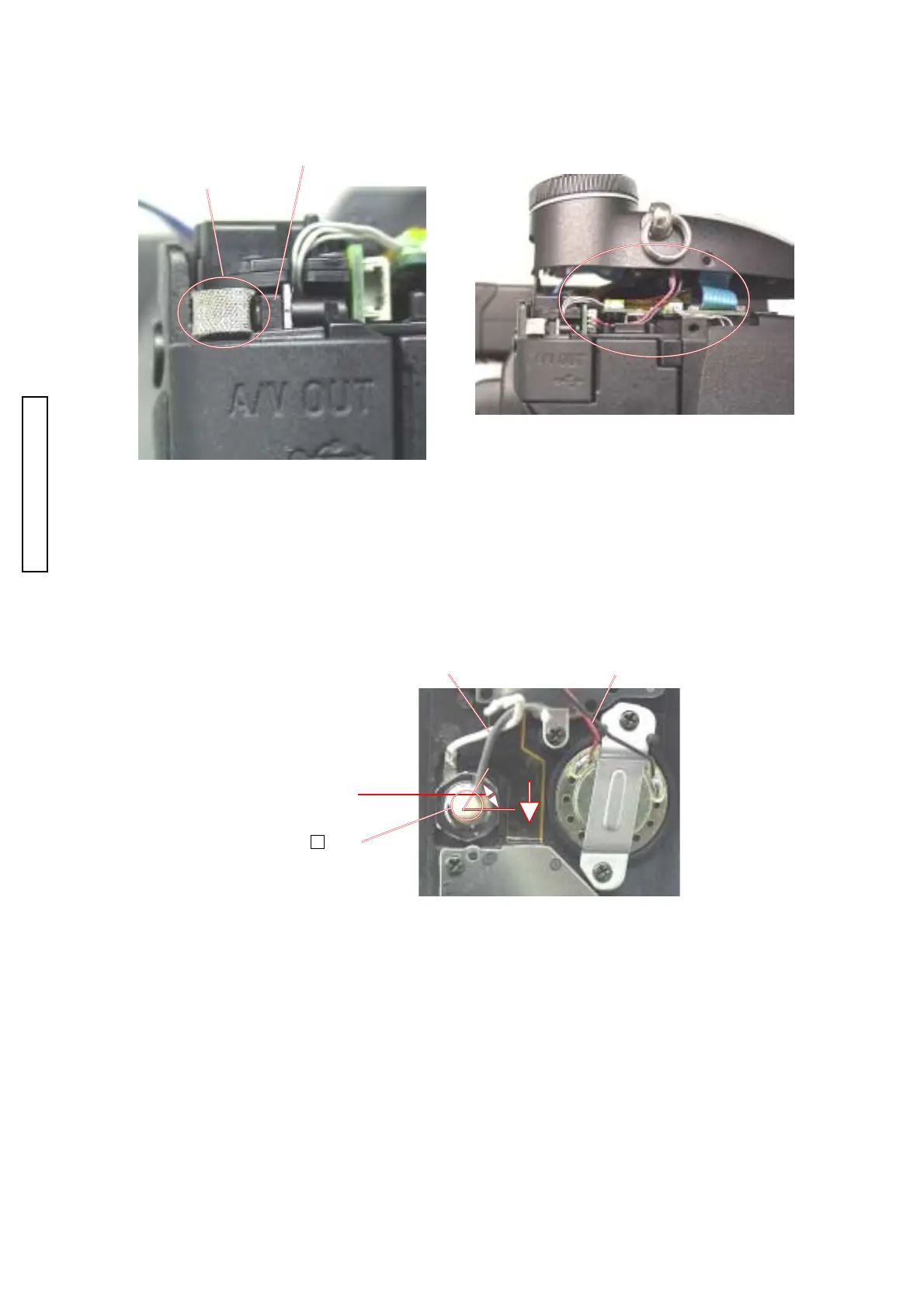
1. Solder the lead wire and harness and arrange them as shown on the figure.1. Solder the lead wire and harness and arrange them as shown on the figure.
1. Solder the lead wire and harness and arrange them as shown on the figure.1. Solder the lead wire and harness and arrange them as shown on the figure.
1. Solder the lead wire and harness and arrange them as shown on the figure.
2. Apply B-10 as shown on the figure.2. Apply B-10 as shown on the figure.
2. Apply B-10 as shown on the figure.2. Apply B-10 as shown on the figure.
2. Apply B-10 as shown on the figure.
3. Press the FPC of the control side unit in the arrowed direction to prevent it from unstableness.3. Press the FPC of the control side unit in the arrowed direction to prevent it from unstableness.
3. Press the FPC of the control side unit in the arrowed direction to prevent it from unstableness.3. Press the FPC of the control side unit in the arrowed direction to prevent it from unstableness.
3. Press the FPC of the control side unit in the arrowed direction to prevent it from unstableness.
Lead wireLead wire
Lead wireLead wire
Lead wire
HarnessHarness
HarnessHarness
Harness
Lead wire (Gray):Lead wire (Gray):
Lead wire (Gray):Lead wire (Gray):
Lead wire (Gray):
Solder them withSolder them with
Solder them withSolder them with
Solder them with
about 45 degrees.about 45 degrees.
about 45 degrees.about 45 degrees.
about 45 degrees.
Assy cabi backAssy cabi back
Assy cabi backAssy cabi back
Assy cabi back