(2720)A 9
2782-11382782-1138
2782-11382782-1138
2782-1138
2782-11392782-1139
2782-11392782-1139
2782-1139
2782-11402782-1140
2782-11402782-1140
2782-1140
33
33
3
±±
±±
±
1mm1mm
1mm1mm
1mm
2782-11422782-1142
2782-11422782-1142
2782-1142
2782-1143 (2)2782-1143 (2)
2782-1143 (2)2782-1143 (2)
2782-1143 (2)
2782-1143 (2)2782-1143 (2)
2782-1143 (2)2782-1143 (2)
2782-1143 (2)
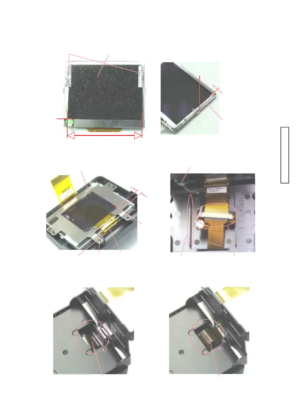
Fig. 1 Assembly of assy cabi backFig. 1 Assembly of assy cabi back
Fig. 1 Assembly of assy cabi backFig. 1 Assembly of assy cabi back
Fig. 1 Assembly of assy cabi back
Assembly of LCD partAssembly of LCD part
Assembly of LCD partAssembly of LCD part
Assembly of LCD part
1. Stick 2782-1142 and 2782-1143 as shown on the figure. 1. Stick 2782-1142 and 2782-1143 as shown on the figure.
1. Stick 2782-1142 and 2782-1143 as shown on the figure. 1. Stick 2782-1142 and 2782-1143 as shown on the figure.
1. Stick 2782-1142 and 2782-1143 as shown on the figure.
0.5mm form LCD surface0.5mm form LCD surface
0.5mm form LCD surface0.5mm form LCD surface
0.5mm form LCD surface
ConnectorConnector
ConnectorConnector
Connector
Turn up to the back.Turn up to the back.
Turn up to the back.Turn up to the back.
Turn up to the back.
Center of LCDCenter of LCD
Center of LCDCenter of LCD
Center of LCD
2. Stick 2782-1140, 2782-1138 and 2782-1139 as shown on the figure. 2. Stick 2782-1140, 2782-1138 and 2782-1139 as shown on the figure.
2. Stick 2782-1140, 2782-1138 and 2782-1139 as shown on the figure. 2. Stick 2782-1140, 2782-1138 and 2782-1139 as shown on the figure.
2. Stick 2782-1140, 2782-1138 and 2782-1139 as shown on the figure.
3. Attach the connector. The harness should not be on the rib on the figure.3. Attach the connector. The harness should not be on the rib on the figure.
3. Attach the connector. The harness should not be on the rib on the figure.3. Attach the connector. The harness should not be on the rib on the figure.
3. Attach the connector. The harness should not be on the rib on the figure.
HarnessHarness
HarnessHarness
Harness
RibRib
RibRib
Rib
ConnectorConnector
ConnectorConnector
Connector
Cover 2782-1140 completely.Cover 2782-1140 completely.
Cover 2782-1140 completely.Cover 2782-1140 completely.
Cover 2782-1140 completely.
4. Let the assy flexible PWB LCD be stuffed in the groove. 4. Let the assy flexible PWB LCD be stuffed in the groove.
4. Let the assy flexible PWB LCD be stuffed in the groove. 4. Let the assy flexible PWB LCD be stuffed in the groove.
4. Let the assy flexible PWB LCD be stuffed in the groove.
(OK) Assy flexible PWB LCD(OK) Assy flexible PWB LCD
(OK) Assy flexible PWB LCD(OK) Assy flexible PWB LCD
(OK) Assy flexible PWB LCD
is put in the is put in the
is put in the is put in the
is put in the
groove.groove.
groove.groove.
groove.
(NG) Assy flexible PWB LCD(NG) Assy flexible PWB LCD
(NG) Assy flexible PWB LCD(NG) Assy flexible PWB LCD
(NG) Assy flexible PWB LCD
is raisedis raised
is raisedis raised
is raised
..
..
.