10 (2720)A
REPAIR GUIDE
2782-1151, 2782-11552782-1151, 2782-1155
2782-1151, 2782-11552782-1151, 2782-1155
2782-1151, 2782-1155
G G-60G G-60
G G-60G G-60
G G-60
G G-60G G-60
G G-60G G-60
G G-60
2782-11562782-1156
2782-11562782-1156
2782-1156
G G-60G G-60
G G-60G G-60
G G-60
2782-11342782-1134
2782-11342782-1134
2782-1134
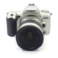
Fig.2 Assembly of the assy cabi back.Fig.2 Assembly of the assy cabi back.
Fig.2 Assembly of the assy cabi back.Fig.2 Assembly of the assy cabi back.
Fig.2 Assembly of the assy cabi back.
Installation of LCD partInstallation of LCD part
Installation of LCD partInstallation of LCD part
Installation of LCD part
1. Stick the assy flexible PWB LCD with 2782-1134 as shown on the figure.1. Stick the assy flexible PWB LCD with 2782-1134 as shown on the figure.
1. Stick the assy flexible PWB LCD with 2782-1134 as shown on the figure.1. Stick the assy flexible PWB LCD with 2782-1134 as shown on the figure.
1. Stick the assy flexible PWB LCD with 2782-1134 as shown on the figure.
Assy flexible PWB LCDAssy flexible PWB LCD
Assy flexible PWB LCDAssy flexible PWB LCD
Assy flexible PWB LCD
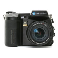
2. Apply G-60 to the axis part (two points on the left and right side) of the assy joint. 2. Apply G-60 to the axis part (two points on the left and right side) of the assy joint.
2. Apply G-60 to the axis part (two points on the left and right side) of the assy joint. 2. Apply G-60 to the axis part (two points on the left and right side) of the assy joint.
2. Apply G-60 to the axis part (two points on the left and right side) of the assy joint.
3. Apply G-60 to the shaded parts of 2782-1151 and 2782-1155.3. Apply G-60 to the shaded parts of 2782-1151 and 2782-1155.
3. Apply G-60 to the shaded parts of 2782-1151 and 2782-1155.3. Apply G-60 to the shaded parts of 2782-1151 and 2782-1155.
3. Apply G-60 to the shaded parts of 2782-1151 and 2782-1155.
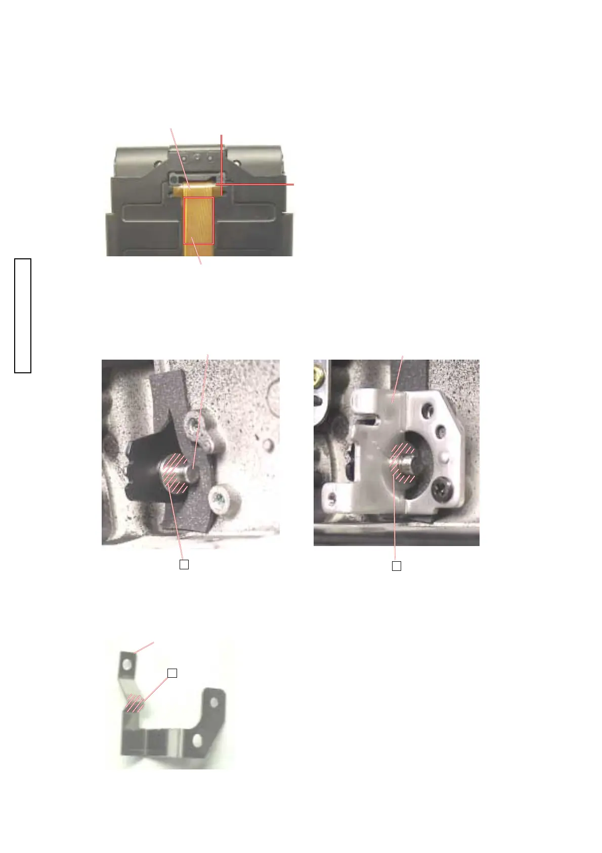
4. Apply G-60 to the click part of 2782-1156.4. Apply G-60 to the click part of 2782-1156.
4. Apply G-60 to the click part of 2782-1156.4. Apply G-60 to the click part of 2782-1156.
4. Apply G-60 to the click part of 2782-1156.
Assy jointAssy joint
Assy jointAssy joint
Assy joint