Installation and Programming Manual
Mircom Technologies Inc All Rights Reserved LT-1034 Rev.1
Page 11 of 54
DO NOT USE A POWER CORD OR ANY OTHER PLUGGABLE DEVICE. Ground the enclosure using the
ground lug in the lower left corner of the enclosure. Do not splice any power connections inside the NMC
enclosure.
Minimum Wire Size: 18 AWG Shielded Cable
Maximum Cable Length: 1,000 feet
OPERATION:
WARNING: As per UL/ULC regulations: When the NMC is triggered for alarm by the FACP, either in
Master Mode or Slave Mode, NO other initiating devices may be wired to the NMC zone inputs.
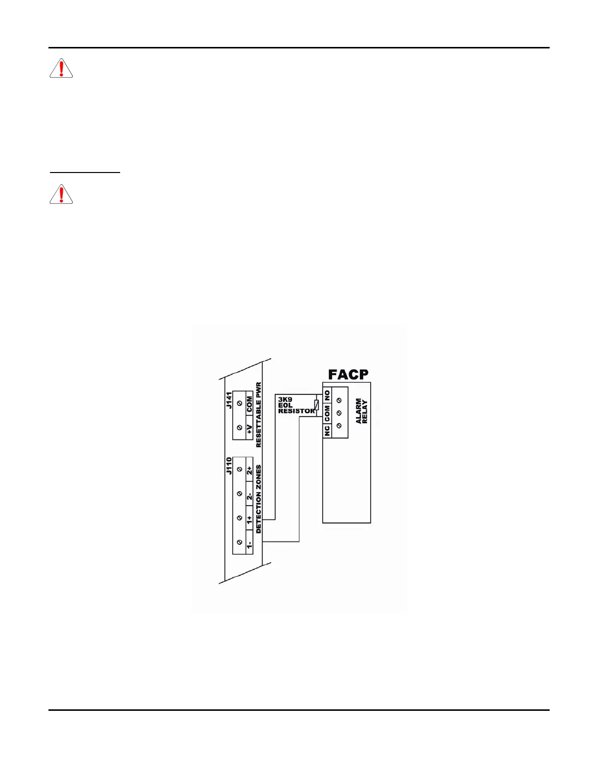
2.2 Master Mode
In Master Mode, when an alarm occurs, the NMC requires the pressing of both the ‘ALARM SILENCE’ and
‘RESET’ buttons to silence the ISDs and reset the alarm condition. Using Zone 1 (or Z2) inputs and the FACP Dry
Alarm Contact Relay, connect zone wires to relay’s common and normally open terminals with a 3.9K ohm, ¼
watt resistor in parallel (across the terminals) to supervise the wires. See
Figure 1 below for the wiring
schematic.
Figure 1- NMC-Master Unit Wiring

 Loading...


