Installation and Programming Manual
Mircom Technologies Inc All Rights Reserved LT-1034 Rev.1
Page 12 of 54
2.3 Slave Mode (Preferred method in Canada)
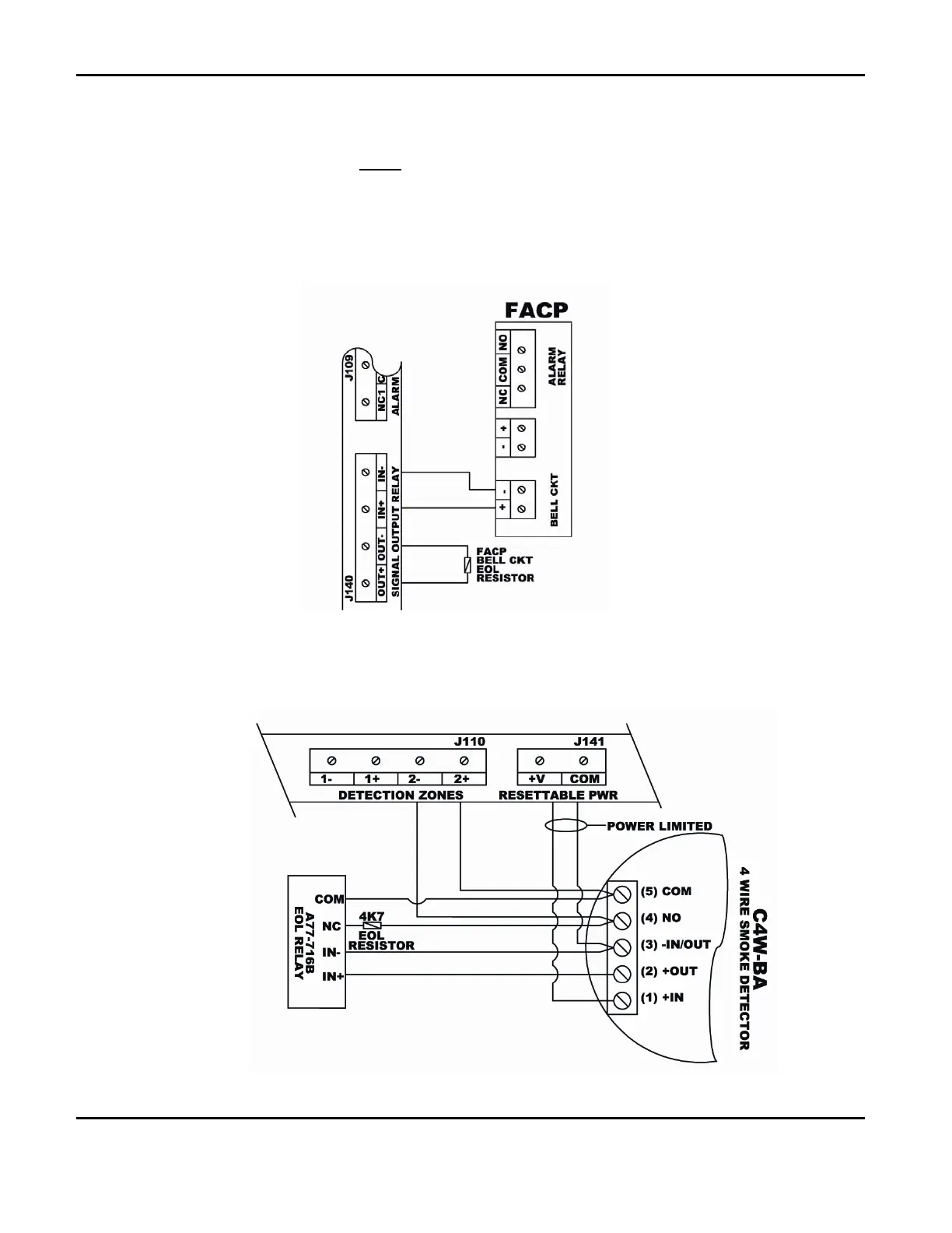
In Slave Mode, the NMC is wired into a spare FACP signal circuit. When an alarm condition occurs, the reversal
of the bell output polarity will cause the NMC to alarm as well. When the FACP Signal Circuits are silenced, the
NMC Bell Output Relay will reset to ‘normal state’ causing the NMC to silence the ISDs and return from alarm
state to normal state. If the FACP re-alarms, this will cause the NMC to re-alarm as well. Connect the Signal
Circuit wiring of the FACP to the NMC Bell Output Relay IN+ and IN- terminals, observing polarity. Wire the FACP
signal circuit end of line resister to the NMC OUT+ and OUT- terminals.
Figure 2 below shows the wiring
schematic.
Figure 2- NMC- Slave Unit Wiring
2.4 Alarm Zones
See Figure 3 below for wiring schematic. NOTE: The resettable power terminal has an output voltage range
of 10.70VDC to 20.27VDC.
Figure 3- 4 Wire Smoke Detector

 Loading...


