Adding and Configuring Amplifiers/Zones
20
Adding and Configuring Amplifiers/Zones
Understanding the Amplifiers/Zones List
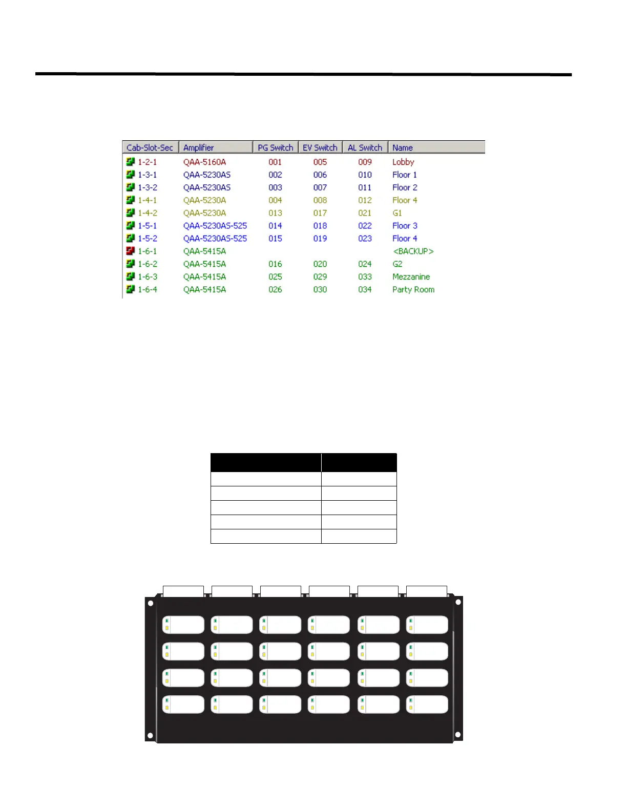
To access the Amplifiers/Zones configuration list, select “Amplifier/Zones” from the left pane. The right pane displays
the system zones/amplifiers.
Amplifier/Zones List Description
• The first column “Cab-Slot-Sec” shows the cabinet number, the slot number and the section number of the
zone.
• The second column shows the Amplifier model installed in this location.
• The third, fourth and fifth columns show the Paging, Evacuation and Alert Switch numbers assigned for that
amplifier section (zone).
• The last column shows the Name of the zone.
List Color Coding
Zones in the list display in colors according to their amplifier model.The backup amplifier will have a red symbol
instead of the green/brown one.
Setting up the Switches
Switches are numbered according to the following diagram.
Amplifier Model Item Color
QAA-5160 Red
QAA-5230A Brown
QAA-5230-AS Dark Blue
QAA-5230AS-525 Light Blue
QAA-5415A Green
PAGE
#1
PAGE
#2
PAGE
#4
PAGE
#3
PAGE
#5
PAGE
#6
PAGE
#8
PAGE
#7
PAGE
#9
PAGE
#10
PAGE
#12
PAGE
#11
PAGE
#17
PAGE
#18
PAGE
#20
PAGE
#19
PAGE
#13
PAGE
#14
PAGE
#16
PAGE
#15
PAGE
#21
PAGE
#22
PAGE
#24
PAGE
#23

 Loading...


