QX-5000 Windows Configuration Utility User Guide
23
Adding and Configuring Inputs
Understanding the Inputs List
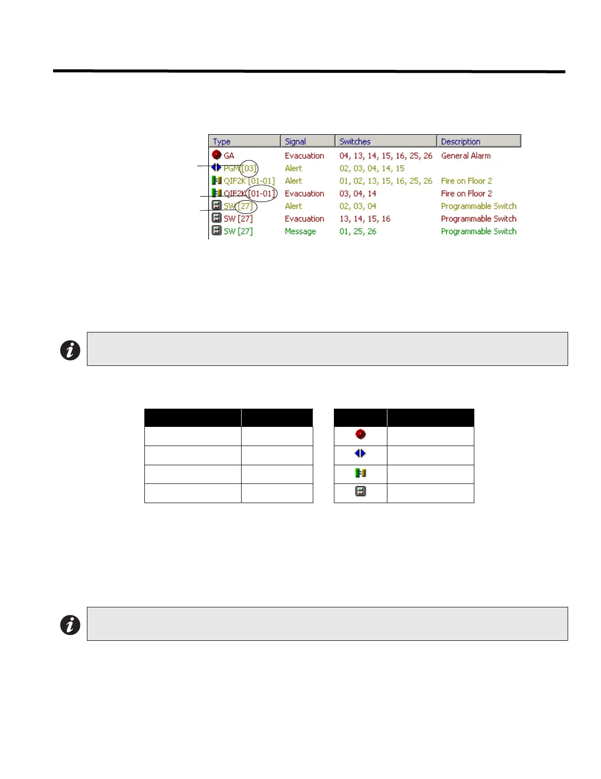
To access the Inputs configuration list, select “Inputs” from the left pane. The right pane displays the system inputs
list.
Inputs List Description
• The first column displays the input Type.
• The second column displays the Signal that the input will generate.
• The third column displays the paging Switches assigned for that input.
• The fourth column displays the Description.
List Color Coding and Symbols
Items in the list display in colors according to their signal type.
About Switch Inputs
When adding a new amplifier, the utility will automatically set all sections’ switches to the next available un-used
switches. If there are no free switches, the value of 1 will be used instead.
When adding new switch inputs, the utility will automatically show the next available un-used switch. If there are no
available switches, the utility will display the value of 1. The specified switch must not be used by the QDV-1000, a
QIF-1000, or a zone. The utility will check the specified switch and prompt you if it cannot be used.The QDV
Installed checkbox in the System Configuration Window (see page 19 for details) has no effect on this restriction.
About Programmable Input #4
If there is a QDV installed and any of its messages repeat time is not set to 255 (forever), Programmable Input #4
cannot be used. This is because of the physical connection between that input and the QDV. Although the utility will
allow you to configure this input, the validation process will reject it if the above condition it true.
Note: The switches column indicates the paging switch numbers that you designate to the listed input when
you set up the amplifier properties (see previous page).
Signal Item Color Symbol Input Type
Evacuation Red General Alarm
Alert Brown Programmable
Paging Blue QIF-2000
Message Green Switch
Note: Only switches 1 to 72 are allowed to be used as input switches.
Programmable Input #
ID# - Input #
Switch #

 Loading...


