20/1531-ASP11301 Uen B5 2017-03-23 36
I
NSTALLING CABINET
Table 14 Mounting Set for 1U chassis, MX-ONE Service Node
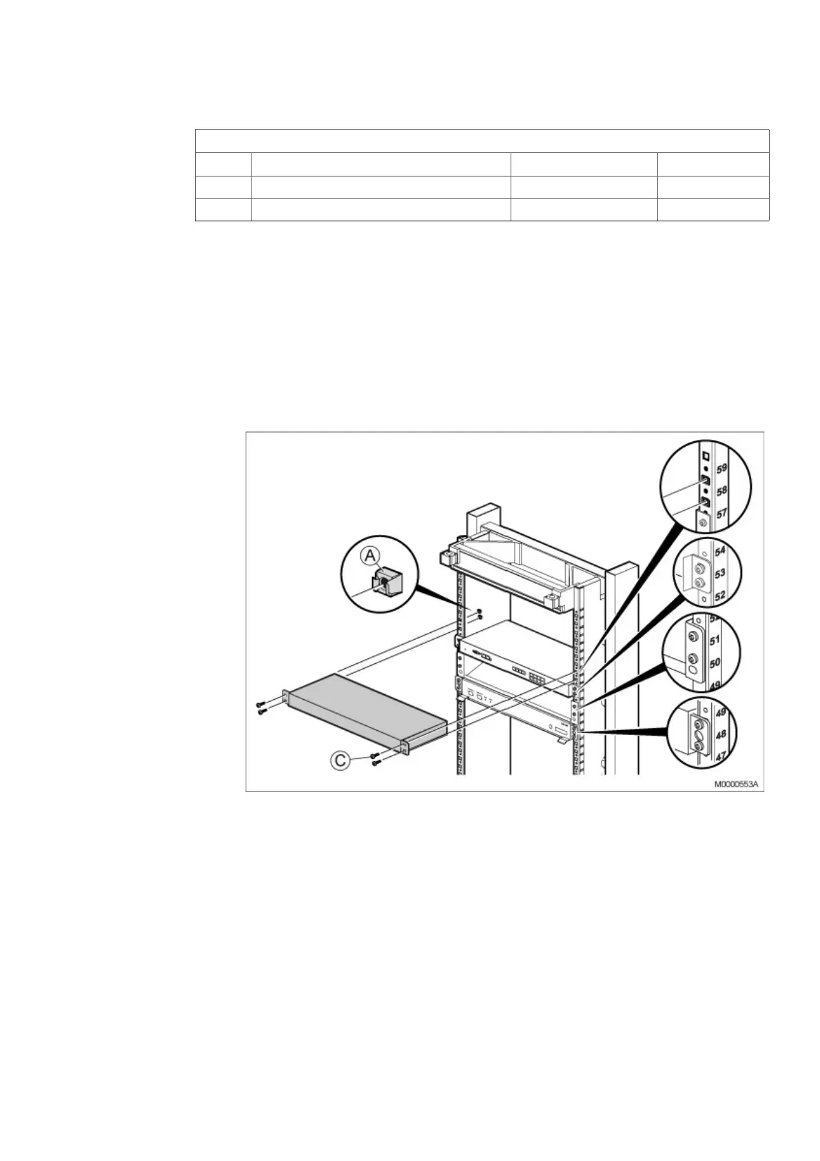
To install the 1U chassis in the cabinet, perform the following steps:
Note: Power inlets are positioned on rear side of the chassis. Secure that rear side is
accessible after mounting, or insert the 48V and/or the 115/230V Mains cable
before mounting in the rack. Fasten all power cables by Cable tie to avoid
disconnection. See Figure 30:Secure Main cables on page 37.
Note: This equipment have to be connected to protective ground. Connect a
grounding cable to the bracket at the earthing point, close to the earthing symbol
located at the rear side of the chassis. See Figure 30:Secure Main cables on
page 37.
Figure 29: Installing MX-ONE 1U chassis
1. Mount four captive nuts (A) (see 2.3 Installing Supporting Captive Nuts on page
18) according to the number positions shown, see on page 36.
2. Fasten the 1U chassis to the four captive nuts in the cabinet, using the four
screws (C).
3. If required, install additional 1U chassis directly above the first one in the next
available cabinet position. No gap is needed between the units.
Note: Do not obstruct the cooling air flow, which goes from right to left in the MX-ONE
Lite (3U) and MX-ONE 1U subrack.
NTM 144 264 Mounting set
Pos Title/Function Product Number Quantity
C SCREW M 6X16 78/SBA 121 060/0160 4
A CAPTIVE NUT M6 SBM 173 060/03 4