4 SAFETY MONITORING FUNCTIONS
4-58 Safety Monitoring Functions
(3) Configuring monitoring conditions
(a) Speed monitoring position
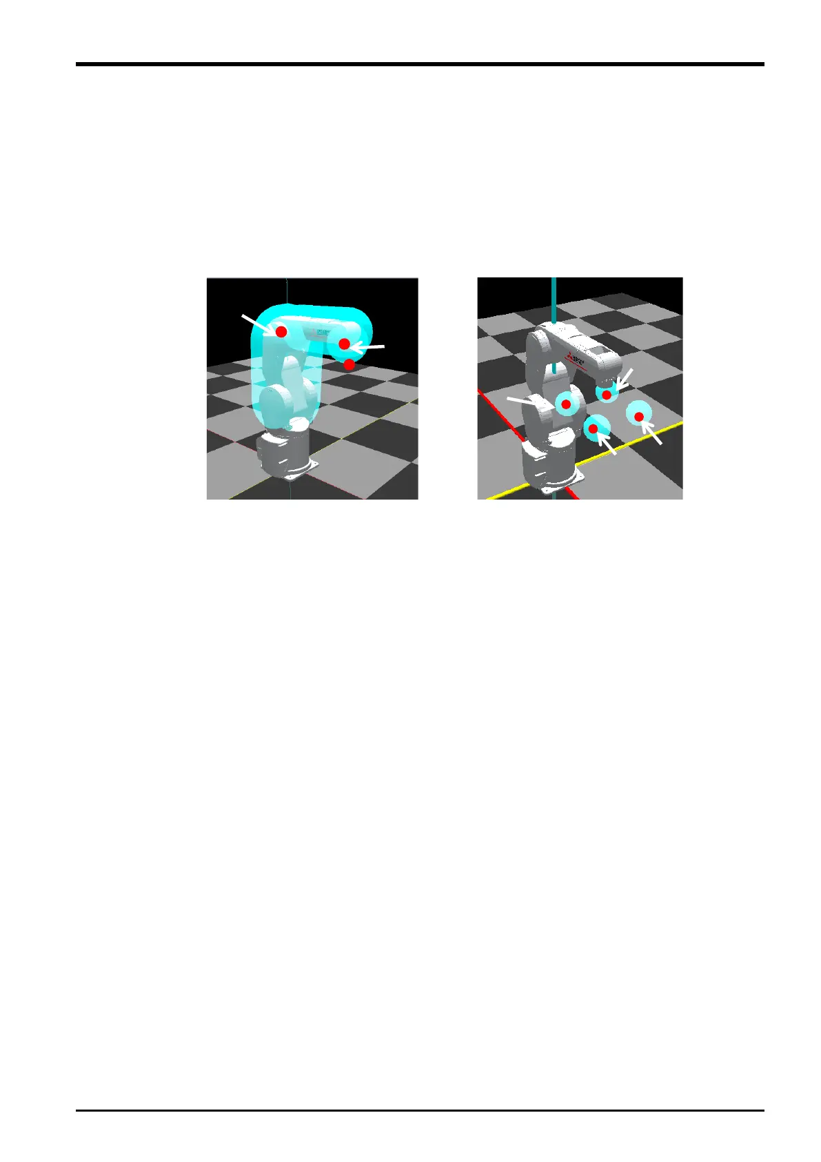
Positions subject to robot speed monitoring are defined with an arm model and tool models. For configuration
of an arm model and tool models, see 4.3 Defining 3D Models. Positions subject to monitoring on an arm
model are A1, A2, and the origin of the mechanical interface coordinates in the figure below. Positions subject
to monitoring on tool models are T1, T2, T3, and T4 in the figure below.
Set the speed monitoring position at the point where the maximum speed can be monitored when the robot
moves.
Fig. 4-47: Speed monitoring position
The origin of
the mechanical
interface
The center of the
sphere models
The center of the
sphere models
 Loading...


