4 SAFETY MONITORING FUNCTIONS
Safety Monitoring Functions 4-69
④ Monitoring Position
This enables selecting a monitoring position of the robot subject to position monitoring.
Selecting [Whole Arm and Tool] enables the position monitoring that uses an arm model and tool models
defined in 4.3 Defining 3D Models.
Selecting [Tool Only] enables the position monitoring that only monitors tool models.
⑤ Monitoring Function To Apply the Plane
This enables selecting monitoring functions (SLP1, SLP2, SLP3, SLPM) to which the monitoring plane
is applied. Multiple functions can be selected.
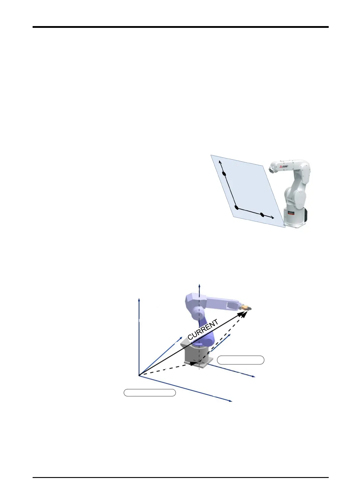
⑥ Plane Definition
As shown in the right figure, configure X, Y, Z
coordinates of the three points (origin, +X axis position,
+Y axis direction) on the defined plane in the base
coordinate system.
The plane is defined in the base coordinate system.
Therefore, the base conversion does not change the
relative position of the robot to the position monitoring
plane.
<Base coordinate system>
The base coordinate system is a coordinate system
based on the robot installation surface. The center of
the robot installation position (base data) in the world
coordinate system can be changed by using parameter
MEXBS or executing the Base command. By default,
the world coordinate system and the base coordinate
system are placed at the same position.
Fig. 4-59: Plane Definition
Fig. 4-60: Base coordinate system
+X axis
direction
 Loading...


