4 SAFETY MONITORING FUNCTIONS
4-68 Safety Monitoring Functions
(3) Configuring monitoring conditions
(a) Arm model and tool model
Monitoring targets can be configured as a sphere model or cylinder model fixed to the robot or hand.
Change in an arm model can only be made to the size. For tool models, free configuration of up to four
sphere models is supported. For configuration of robot monitoring positions and hand monitoring positions,
see 4.3 Defining 3D Models.
(b) Safety monitoring plane
SLP monitoring planes for position monitoring can be configured. Definition of up to eight planes is
supported.
Fig. 4-57: Safety monitoring plane
① Plane Setting
This enables selecting a monitoring plane to be configured or changed from the pull-down menu. (Plane
1 to Plane 8)
② Plane Monitoring
This sets the plane monitoring to Enable or Disable. Only the planes set to Enable are monitored.
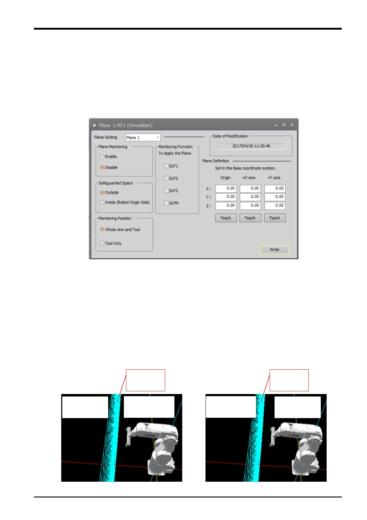
③ Safeguarded Space
This specifies the side of a monitoring plane on which the safeguarded space (that allows no movement)
is placed. To set the safeguarded space on the opposite side of the origin of the robot, select Outside.
To set the safeguarded space on the side of the origin of the robot, select Inside. (See the figure below.)
Fig. 4-58: Safeguarded space setting
 Loading...


