Set up the robot arm Installation
3 - 20
RH-3SDHR and RH-3SQHR
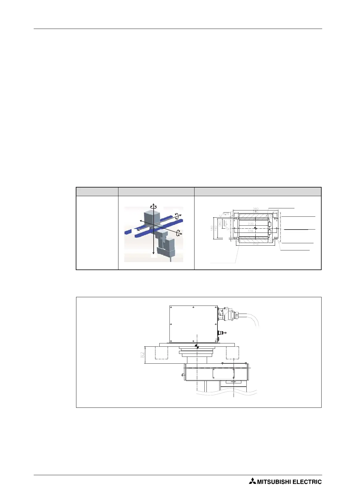
The table below shows how to set up and fix the SCARA robots RH-3SDHR and RH-3SQHR.
The robot installation surface has been machine finished.
If the installation surface is too uneven then this may result in robot arm malfunctions.
Use the installation holes (4-Ø9) opened at the four corners of the base, and securely fix the robot
with the enclosed installation bolts (hexagon socket bolts).
Align the robot arm horizontally.
The surface roughness of the assembly surface should be Rz25 or more. If the surface is too rough
then this may result in deviations in the position of the robot arm.
To avoid position deviations, the peripheral equipment that the robot accesses as well as the robot
arm itself should be installed on a common assembly platform/area.
The installation surface must be designed so that no distortion can occur, even from the loads
and vibrations emanating from the robot itself.
Only remove the transport locks and hanging tools after setting up the robot arm.
High loads and strains occur on the installation surface when operating the robot at high speeds.
Make sure that the base area is suitable for the high forces and moments, as listed in Tab. 3-7.
The interference of installation bolt and No.1 arm may occur depending on the size of installation
stage. Take care against interference of installation bolt, such as inserting the installation bolt
from the bottom.
Robot arm Fixture View from above
RH-3SDHR,
RH-3SQHR
R001783E R001784E
Tab. 3-6: Hanging the robot arm
R001785E
Fig. 3-13: Mounting the robot to the installation stage
FV
MT
FH
ML
FH
ML
FH
FH
FV
Installation side
(standard)
4-Ø9 installation
hole
Maintenance space
2-M12 hole for
hanging tools
4-M8 hole for the
jackup
Installation stage
(example)
Maintenance space
Installation side
(standard)
 Loading...


