19
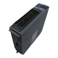
2.2 Internal I/F Connector
Use the internal I/F connector on the front of the Motion controller to connect to manual pulse
signals and incremental synchronous encoder signals.
The pin layout of the Q170MSCPU's internal I/F connector
The following is the pin layout of the internal I/F connector as viewed from the front.
*1 Differential-output type
Connect the A-phase signal to HAH, and the A-phase inverse signal to HAL.
Connect the B-phase signal to HBH, and the B-phase inverse signal to HBL.
*2 Voltage-output/open-collector type
Connect the A-phase signal to HA, and the B-phase signal to HB.
*3 Input type from manual pulse generator/Incremental synchronous encoder is switched by SEL.
Not connected: Voltage-output/open-collector type
SEL-SG connection: Differential-output type
*4 "COM1" is the common terminal of DI1, DI2, DI3 and DI4.
*5 "COM2" is the common terminal of DO1 and Do2.
*6 Do not connect anything to the terminals listed as "No connect".
*7 Do not use the 5V terminals for applications other than power supply for manual pulse generator/incremental
synchronous encoder.
Applicable connector model name
Wire size
•AWG28
Pin layout Pin No. Signal name Pin No. Signal name
26 HAL
*1
13 HBL
*1
25 HAH
*1
12 HBH
*1
24 HA
*2
11 HB
*2
23 No connect
*6
10 SEL
*3
22 SG 9 5V
*7
21 No connect
*6
8 No connect
*6
20 No connect
*6
7 No connect
*6
19 No connect
*6
6 No connect
*6
18 No connect
*6
5 No connect
*6
17 DI3 4 DI4
16 DI1 3 DI2
15 COM1
*4
2COM2
*5
14 DO1 1 DO2
Type Model Manufacturer
connector connector case
Soldering type connector
(LD77MHIOCON)
10126-3000PE 10326-52F0-008 3M Japan Limited make

 Loading...


