Do you have a question about the Mitsubishi 4D68 and is the answer not in the manual?
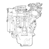
Detailed diagrams illustrating the engine's internal components and layout.
Key technical specifications of the 4D68 engine, including displacement, bore, stroke, and compression ratio.
Detailed measurement specifications for engine components during service and repair.
Specifications for oversized components and machining tolerances for cylinder head parts.
Torque values for various fasteners across different engine systems, crucial for assembly.
Procedures for plastic area tightening, sealant, and form-in-place gaskets.
Comprehensive list of specialized tools required for engine repair and maintenance.
Step-by-step procedures for removing and installing the drive belt and glow plugs.
Key service points for removal/installation and inspection procedures for glow plugs.
Detailed procedures for timing belt removal, installation, and adjustment.
Critical service points and cautions for timing belt removal and component loosening.
Guidelines for inspecting timing belts and pulleys for wear or damage.
Procedures for removing and installing glow plugs, fuel injection pump, and nozzles.
Key service points for the removal and installation of injection pipes, fuel pump, and nozzles.
Procedures for removing and installing intake and exhaust manifolds and related components.
Installation guidance for oil return pipe gaskets, eyebolts, and EGR pipe gaskets.
Step-by-step instructions for removing and installing water pump, thermostat, hoses, and pipes.
Specific installation procedures for thermostat housing, water outlet, thermostat, and covers.
Procedure for installing the engine coolant temperature gauge unit, including sealant application.
Procedures for removing and installing rocker arms, rocker shaft, and camshaft components.
Detailed steps for adjusting valve clearance, including standard values and procedures.
Inspection checks for camshaft height and rocker arm shaft condition.
Procedures for removing and installing the cylinder head, valves, and valve springs.
Detailed steps for installing cylinder head bolts, including torque and angle tightening.
Procedures for checking and measuring valves, springs, guides, and seats.
Steps for reconditioning and replacing valve seats.
Steps for removing, reboring, and press-fitting valve guides.
Procedures for removing and installing front case, counterbalance shafts, and oil pan.
Procedures for installing counterbalance shaft bearings.
Installation of front case, oil pump seals, and flange bolts.
Inspection of counterbalance shafts, oil pump, and oil seals.
Procedures for removing and installing pistons and connecting rods.
Assembling and installing pistons, rings, pins, and connecting rods.
Procedures for installing connecting rod cap nuts using plastic area tightening method.
Inspection of piston rings and crankshaft pin oil clearance.
Procedures for replacing connecting rod bushings using special tools.
Procedures for removing and installing the crankshaft, cylinder block, and flywheel.
Selecting and installing crankshaft bearings based on journal and bore identification marks.
Installing bearing caps and bolts, including torque and angle tightening procedures.
Inspecting and boring the cylinder block, including sleeve procedures.
Checking piston protrusion and cylinder block condition after assembly.
| Brand | Mitsubishi |
|---|---|
| Model | 4D68 |
| Category | Engine |
| Language | English |