α
Simple Application Controllers
Function Block Diagram (FBD) Operation 6
6-4
6.2.7 Placing the Blocks on the FBD Base
To place the Function Blocks or Si
nals on the FBD base, left click once on the icon and move
the mouse to the desired location for the icon to be placed. The arrow should turn into a
crosshair when pulled over the FBD base border. Left click to install the icon.
An ERROR dialo
box will appear to detail an
errors in block placement.
6.2.8 Moving Function Blocks and Signals
Function Blocks and Si
nals can be moved after the
have been placed on the FBD base b
left clickin
on the icon and dra
in
the icon with the left button depressed. When the left
button is released, the icon will be dropped in the new position. Blocks can onl
be moved
inside the FBD base. Wirin
connections will move with the icon.
Ille
al operations will be explained via a dialo
box and the icon will be returned to its previous
position.
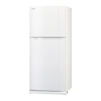
6.2.9 Output Blocks
The s
stem outputs should be placed in the output rectan
les on the ri
ht side
of the FBD base. Ouputs placed outside the rectan
les will act as neutral
blocks. There are two, four, or ei
ht outputs available dependin
on the t
pe of
controller chosen. The outputs blocks have one input pin and an output pin
that can connect to other function blocks or outputs.
Four AS-Interface outputs, A01 - A04, are available when usin
the 20 I/O
versions of the Alpha controller and VLS Version 1.30 or above. These
Outputs can be placed an
where on the FBD base and will not count towards
the number of s
stem outputs.
6.3 The Wiring Tool
The wirin
tool
raphicall
represents, in the form of terminated lines, the
connections made between the pins of inouts, outputs, si
nals and
functions present in the FBD window.
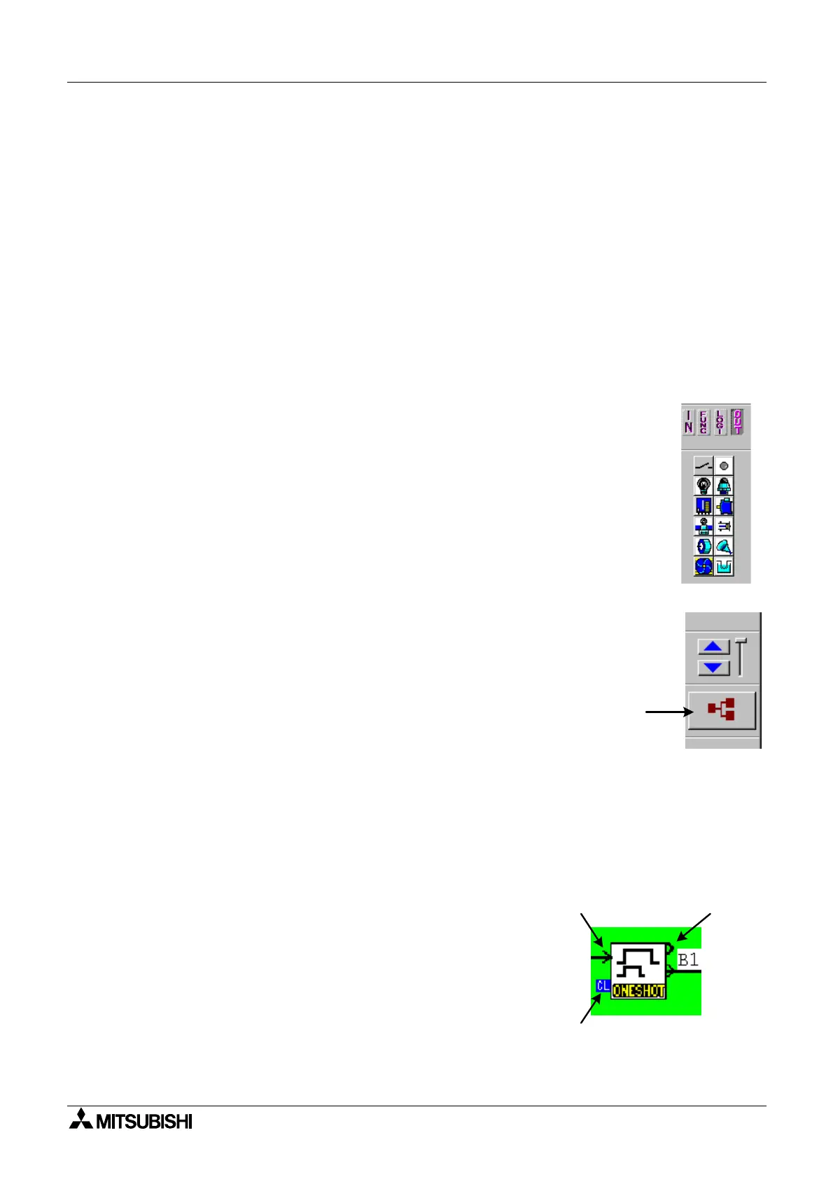
6.3.1 Input and Output Pins
The small icons present on left and ri
ht side of Si
nal/Function icon are known as pins. Pins
are of two types, BIT (Di
ital) pins and WORD (Analo
) pins. Pins which are present on the left
side of icon are known as INPUT pins. Pins which are present on the ri
ht side of icon are
known as OUTPUT pins.
Bit Pin
Di
ital Pin
- On or Off si
nals
Clear Pin - Di
ital Pin that resets a counter or condition to 0
Word Pin
Analo
Pin
- Receives/sends numerical data from
Volta
e or Amperes measurements. The pin is enclosed in a
li
ht
reen s
uare on the VLS displa
to differentiate it from a
di
ital pin.

 Loading...