α
Simple Application Controllers
System Sketch Screen Operation 7
7-1
7. System Sketch Screen Operation
‘Monitorin
in S
stem sketch’ is a simple
raphics window. S
stem sketch is useful to
ive the
pictorial view of I/O devices which are connected to the Controller and the associated
pro
rammin
lo
ic. When the Monitorin
in S
stem sketch window is active, the Wirin
tool
bar will be disabled.
The S
stem sketch screen user can draw their own dia
rams, place I/O devices to represent
the Controller set-up, import OLE files, monitor a runnin
α
controller, simulate/check
pro
rammin
lo
ic without a controller, and print S
stem sketch screen data.
7.1 Components of System sketch window
The S
stem Sketch Window has a default rectan
le known as the S
stem Sketch Base
Rectan
le. All the components should be placed within the S
stem Sketch Base Rectan
le.
7.1.1 System sketch Base Resize
The S
stem Sketch Window opens to a minimum default size. The Base can be resized in
width or hei
ht b
dra
in
either the ri
ht or bottom ed
es respectivel
. B
dra
in
the ri
ht
bottom corner of the base rectan
le, the base hei
ht as well as width chan
es. The Base
cannot be resized on left and top ed
es.
Components present in the S
stem Sketch Window are not moved when base is resized.
Hence the Base can be re-sized onl
till the ed
e of ri
ht most or bottom most component.
Base size can be increased to a scroll bar position limit of 30,000.
7.1.2 Changing the Base Color
Choose a new Base Color from the shades available in the Set Base Color command in the
Options Menu.
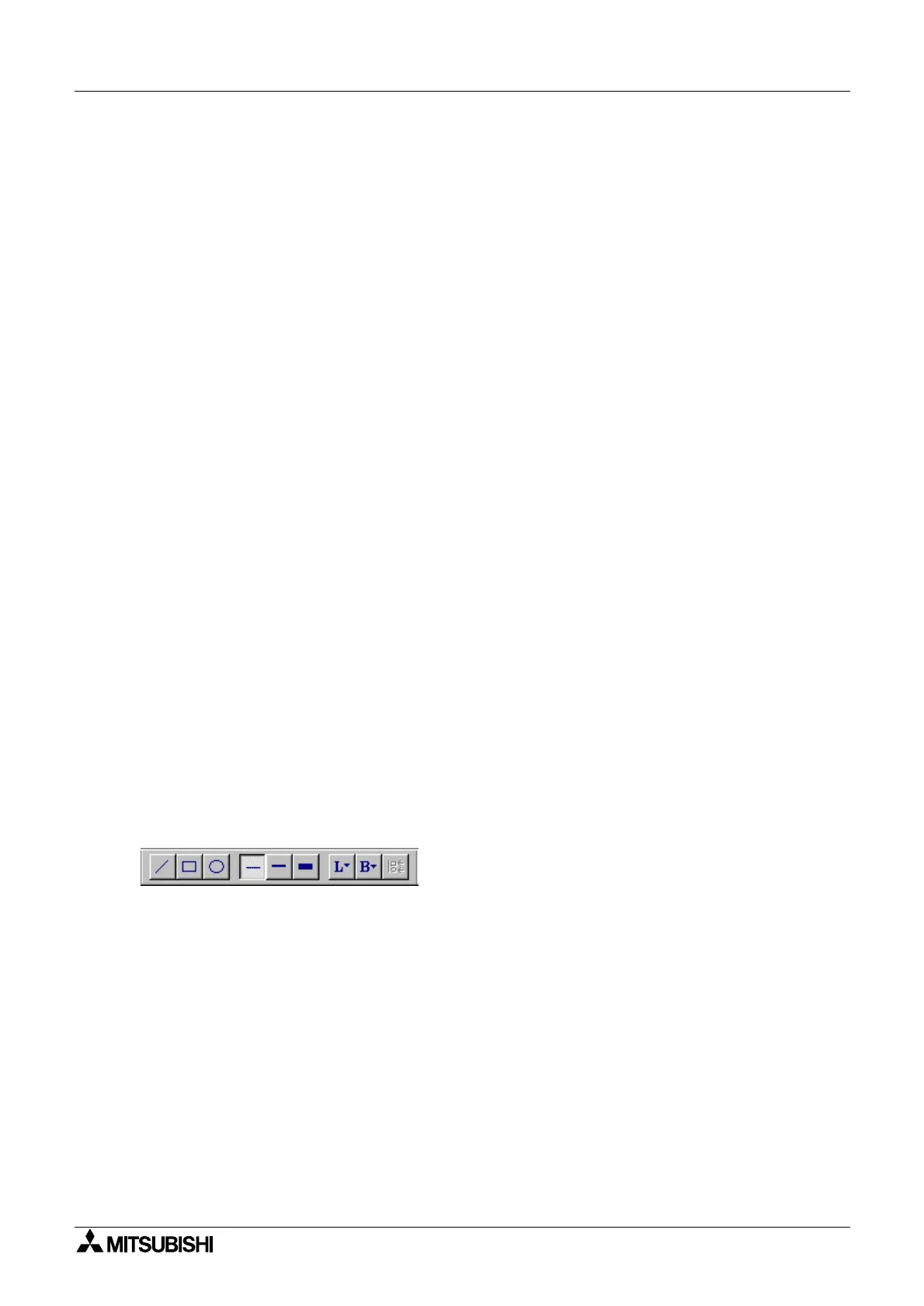
7.1.3 Drawing Lines, Ovals, and Rectangles
Lines can be drawn b
clickin
on the line icon and then movin
the mouse to place for the line
to start. Click the mouse button to start the line and release the button when the desired end
point is reached.
Ovals and Rectan
les can be drawn in the same manner b
choosin
the appropriate icons.
7.1.4 Moving and Resizing Lines, Ovals, and Rectangles
The ob
ects can be moved within the S
stem Sketch base size limit b
clickin
on them and
dra
in
them to the new position. Resizin
can be done b
pressin
the left mouse button on
an
of the ed
es and dra
in
the mouse. The mouse cursor chan
es to double headed arrow
when it is moved over the ed
es indicatin
the direction in which Resizin
can be done.
The ob
ects can be Resized within the boundaries of the S
stem sketch base onl
.
Cut, Cop
, and Paste can be performed on these ob
ects within the S
stem Sketch window.

 Loading...